
There always will be fringe markets for products that use renewable energy to provide marginal heating comfort. These markets survive based on “early adopters” or carbon minimalists who willingly sacrifice superior comfort as the perceived “price” for using renewable energy.
One of my assertions, learned over 40 years of working with a range of renewable energy-based heating systems, is that they will only gain mainstream acceptance if they provide comfort that’s as good if not better than conventional systems. The typical North American consumer will not knowingly sacrifice comfort just to shift the source of their heating energy from conventional to renewable sources.
I also maintain that widespread use of renewable energy-based systems requires that they be economically sustainable without government subsidies and serviceable by any reasonably competent HVAC technician.
Time and again our industry has witnessed attempts at developing renewable energy approaches to central space heating that did not meet one or more of these conditions. Nearly all of them eventually failed to generate a “sustainable” solution that’s as likely to be used in a typical suburban home as it is to stir reader passion in the latest issue of Mother Earth News.
There is no silver bullet solution to these requisite issues of comfort, affordability and reliability. Instead, there are constant refinements of the techniques and hardware we use. The industry must keep striving for solutions that are:
- sophisticated but simple;
- renewable yet reliable;
- ecologically sound and economically sustainable; and
- refined as well as repeatable.
Progress with pellets
Over the last few years I’ve worked on many projects involving wood-pellet boilers. I’ve seen very successful applications as well as situations where the owner eventually just gives up and tells whoever is responsible to “get that thing out of my basement.” Many lessons learned have led to significant improvements and progress toward designs that meet all the bullet points listed above.I’m presenting a concept for a system that embodies many simple but salient details based on these experiences. This system is intended to supply space heating and domestic hot water to residential or light-commercial buildings using a pellet boiler as the renewable energy heat source, and radiant panels as the comfort delivery method. It makes use of contemporary hydronics technology such as variable-speed circulators, stratified thermal storage, hydraulic separation, injection mixing and “on-demand” domestic water heating. It creates conditions that complement rather than compromise the desirable operating characteristics of the pellet boiler and those of the balance-of-system components.
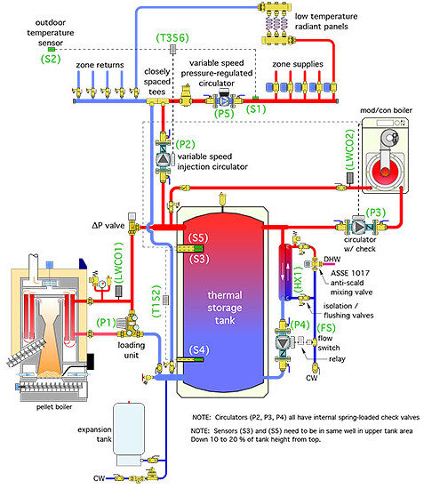
A piping schematic for the system is shown in Figure 1.
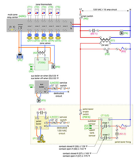
An electrical control diagram is shown in Figure 2.
Please consider both these schematics “starting points.” They are not meant to represent complete system designs. Although they show the majority of the required hardware, designers using them still are responsible for adding specific safety- or code-required devices such as a manual reset high limit on both boilers if the system is used as a commercial application.
System anatomy
This system assumes the use of radiant floor, wall or ceiling panels that can provide design load output using a supply water temperature of 120º F or less. The distribution system has multiple zones, each controlled by a standard zone valve. A variable speed pressure-regulated circulator (P5), operating in constant differential pressure mode, provides consistent flow through each zone regardless of which zones are operating. The fewer the number of active zone circuits, the lower the power demand of the circulator. That’s state-of-the-art “cruise control” for distribution system flow rate along with significant electrical energy savings.
The primary heat source is a modern wood-pellet boiler. It’s combined with a thermal storage tank having a nominal 2 gal. of volume per 1,000 Btu/h of pellet boiler capacity. This tank lets the pellet boiler operate with long on-cycles followed by long off-cycles, which allows the boiler to achieve high thermal efficiency with minimal emissions. A suggested operating scenario is one that provides an average run cycle length of three hours per start. Modern pellet boilers internally log both run time and number of starts so that the boiler’s performance can be verified.
The pellet boiler operates completely independent of calls for heat from zone thermostats. This method of control is obviously different from what the hydronic heating industry is used to. To achieve long on-cycles, the pellet boiler is turned on and off based on the temperatures at two sensors in the thermal storage tank. A single controller (T152) monitors both sensors and allows independent open/close settings for each of its two relay outputs. The pellet boiler is turned on when the upper tank sensor (S3) detects a temperature of 128º or less. The boiler continues to fire until the lower tank sensor (S4) reaches 175º. This operating logic provides a wide swing in tank temperature during each boiler cycle. Wide temperature swings in thermal storage encourage those desired long on-cycles. These temperature set points also maintain the upper portion of the thermal storage tank hot enough to supply domestic hot water whenever it’s needed.
Heat transfer from thermal storage to the distribution system is regulated by a variable-speed injection circulator (P2) with a standard PSC (permanent split capacitor) motor. Heat input varies based on keeping the supply water temperature at sensor (S1) at or very close to a “target” temperature that’s continuously calculated by outdoor reset control logic. Circulator speed control and outdoor reset logic are provided by the (T356) controller.
This system also uses a differential pressure bypass valve (Delta-P valve) set for 1.5 psi to prevent flow through the pellet boiler when it and its associated circulator (P1) are off. This is important since pellet boilers do not use motorized flue dampers to limit off-cycle convective losses up the chimney. The Delta-P valve also prevents reverse thermosiphoning from the thermal storage tank through the boiler and associated piping. It replaces the need for a check valve between the pellet boiler and thermal storage tank.
The pellet boiler is protected against sustained flue gas condensation by a loading unit, which combines a circulator with a thermostatic mixing valve. That valve’s cold port is completely closed when the boiler starts from room temperature. This prevents heated water from flowing to the load or thermal storage tank. Instead, the heated water remains in the boiler loop to bring the boiler’s heat exchanger above the dewpoint temperature of the flue gases as quickly as possible. As the water temperature from the loading unit to the pellet boiler climbs above 115º the cold port of the valve begins to open, while the bypass port (at the top of loading unit) begins to close. The cold port will be fully open and the bypass port completely closed when the water temperature leaving the loading unit reaches 133º or higher.
Backup
The pellet boiler, operating as described above, could provide year-round heat for both space heating and domestic hot water. However, just like any boiler, it could also be down for service when heat is needed or it could be intentionally turned off during warmer weather.
It’s also possible that the pellet boiler would not be sized for the full design heating load. Although that might seem heretical to most boiler specifiers, it’s an acceptable and sometimes required practice with pellet boilers. The underlying objective again is to keep the boiler operating with long on-cycles for high efficiency and low emissions. Boilers that are undersized relative to design load should, in theory, operate essentially 100% of the time during design load conditions. The only time that an undersized pellet boiler should turn off under design load conditions is for automatic cleaning cycles, which typically occur every four to six hours and only last a few minutes. Interestingly, a pellet boiler sized for 75% of a building’s design heating load, in a typical upstate N.Y. climate, should, on average, supply about 96% of that building’s seasonal space-heating energy requirement.
To cover these possibilities, the system includes an auxiliary modulating/condensing boiler. That boiler is piped across the upper portion of the thermal storage tank. This allows it to “exercise” the thermal mass in the upper 10-20% of the tank as a deterrent against short cycling. Temperature stratification in combination with tank piping limits the amount of tank water the auxiliary boiler interacts with. Auxiliary boiler buffering is very important when the distribution system is divided into many zones, some of which may have heating requirements well below the mod/con boiler’s minimum modulation rate. An example would be a small towel warmer radiator, operating in the master bathroom, on a cool fall morning.
Under normal operating conditions, the pellet boiler should maintain a temperature no lower than 128º at the top of the thermal storage tank. However, if it can’t, the mod/con boiler comes to the rescue when the upper tank temperature drops to 125º or lower. Maintaining the hot water reserve at the top of the tank is critical for the on-demand domestic water-heating subsystem, as well as expedient delivery of heat to space-heating zones.
Upon request
Domestic hot water is provided “on-demand” by combining the hot water reserve at the top of the thermal storage tank with a stainless steel heat exchanger mounted outside that tank.
Having the heat exchanger outside the tank allows full servicing or even replacement if necessary. This is not possible with most indirect water heaters using internal coil heat exchangers. An external heat exchanger also can be sized to fully heat cold domestic water to its final delivery temperature when the water temperature at the top of the thermal storage tank is only about 10º higher than that delivery temperature. This allows the mod/con boiler to operate within its condensing range while providing domestic water heating. Contrast that with situations where a mod/con boiler is forced to operate at much higher (non-condensing) water temperatures to compensate for marginal heat transfer through a small internal coil heat exchanger in many indirect water heaters.
A flow switch (FS) in the cold domestic water piping closes whenever the building’s demand for domestic hot water exceeds 0.6 gpm. This turns on circulator (P4) via a relay. Hot water from the top of the thermal storage tank immediately flows through the primary side of the stainless steel heat exchanger (HX1) as cold domestic water flows through the other side. The temperature response time of a brazed-plate heat exchanger is incredibly fast due to its high internal surface area to volume ratio. Fully heated water should be available from the outlet of the heat exchanger three to four seconds after the flow switch closes. The stainless steel brazed plate heat exchanger should be sized to fully heat the domestic water to a minimum 115º delivery temperature based on 125º water available from the top of the tank.
Given the temperature control logic used by the pellet boiler, there will be times when the water temperature in the upper portion of the tank is well above 125º. It could be as high as 190º. Because of this, it’s crucial to provide an ASSE 1017 rated anti-scald valve between the outlet of the domestic water heat exchanger (HX1) and the hot water plumbing system.
Combination isolation/flushing valves are provided so that the domestic side of the brazed-plate heat exchangers can be acid-washed to clean away scale accumulation. The DHW subsystem also includes a pressure-relief valve on the heat exchanger side of the isolation/flushing valves.
Heat migration from the thermal storage tank is minimized by a Delta-P valve between the tank and pellet boiler, a spring-check valve inside circulator (P2) and a spring-check valve in the auxiliary boiler piping.
Next month I’ll provide a full description of operation for this system along with suggested controller settings.
To read Siegenthaler’s article “Bio-radiant heating” in pdf form, please see here
.

