
With nearly all government-related energy programs focused on carbon reduction, fossil fuels are increasingly viewed as the past, somewhat resentfully as the present and highly unlikely as the future. Electricity, on the other hand, is viewed as the increasingly favorable means of connecting large-scale renewable sources such as acres of photovoltaic panels and large wind farms with all types of loads, including heating and cooling.
Given this accelerating transition in how energy is delivered, electrically-driven heat pumps are destined to carve out an increasing percentage of the future residential and light-commercial HVAC markets. This trend is readily apparent in Europe. In Germany, for example, 2017 sales of electrically-driven heat pumps exceeded those of fossil-fuel boilers for the first time.
Heat pumps can be applied in many situations where low-temperature heat is freely available and a load is present to accept that heat at a higher temperature. Heat pumps are used for space heating, domestic water heating, heat-recovery ventilation and even recovering useful heat from sewer effluent.
Most heat pumps used for space heating also have the ability to provide cooling and dehumidification. Thus, selecting a heat pump for space heating often displaces the need for a separate cooling system, as would be required for hydronic systems using boilers.
Everyone loves geo
Geothermal heat pumps that extract heat from ground water, or buried earth loops, have become the “darling” of the North American HVAC market. Government incentive programs in both Canada and the U.S. now offer generous rebates or tax credits that significantly lower the installed cost of geothermal heat-pump systems.
The long-standing “pitch” for use of geothermal heat pumps is the ability to operate at higher coefficients of performance (COPs) relative to air-source heat pumps in cold-climate applications. This advantage became the focus of utility incentive programs during the 1980s. The utilities viewed geothermal heat pumps as a means of “quality load growth.” The ability to increase electrical energy sales while reducing the peak demands associated with electric resistance heat to back up early generation air-source heat pumps during cold weather.
While the COP advantage of geothermal heat pumps generally remains true, the “COP gap” between geothermal and other types of heat pumps has been steadily shrinking, largely due to refinements in “cold climate” air-source heat- pump technology.
The difference in annual space-heating cost between a heat pump with a seasonal average COP of 3.5 vs. a different heat pump with a seasonal average COP of, say, 2.5, shrinks in direct proportion to the building’s design heating load.
Here’s an example based on a recent comparison between two heat pumps. Heat pump No. 1 was a geothermal heat pump with an assumed seasonal average COP of 3.5. Heat pump No. 2 was a cold-climate air-to-water heat pump with a seasonal average COP of 2.5. Both heat pumps were assumed to supply heat to an energy-efficient house in a cold upstate N.Y. climate of 6,720 heating degree days. The design heating load of the house was 18,000 Btu/h.
The electrical energy saved by the higher COP heat pump over the other heat pump was about 2.82 MBtu/h (1 MMBtu = 1 million Btu). With electricity priced at $0.12/kw/h, the annual savings in heating energy was about $99. That’s far less than what most people spend for a year of cell phone service.
The geothermal heat pump with the higher COP does reduce the space-heating cost. However, the question that remains is: Can the significantly higher installation cost of the geothermal heat pump be amortized by the savings it produces over the life of the equipment? Without the subsidies now available for geothermal heat pumps and when competing against unsubsidized low-ambient air-source heat pumps, the economic viability of the higher-performance/high-price heat-pump system remains dubious. Using local costs in upstate N.Y., I find the simple payback of the higher-cost system way beyond an estimated 25-year lifecycle.
Heat pumps + hydronics
No heating technology, regardless of its energy efficiency, will gain and retain market share if it fails to deliver excellent comfort.
Heat pumps that deliver heat using forced-air distribution systems are saddled with many of the same comfort compromises as other forced-air distribution systems. These include potential for temperature stratification, drafts, cool floors, building pressurization that increases air leakage, the sound of forced-air delivery, and dust movement within ducting and living spaces. Good HVAC hygiene such as duct cleaning, use of HEPA filters or electronic air cleaners can reduce dust issues, but the physiological mismatch between a forced-air delivery system vs. properly designed radiant panel systems remains.
So, how do you put together the combination of:
- High energy efficiency in cold-climate applications;
- Renewably-sourced electricity;
- Superior comfort; and
- Unsubsidized economic sustainability?
One solution where these desirable traits converge is a low-ambient air-to-water heat pump combined with a low-temperature radiant panel distribution system.
Current generation low-ambient air-to-water heat pumps can extract useable heat from outdoor air at temperatures down to -8° F. That heat can be transferred to a steam of water or antifreeze solution and supplied to a hydronic radiant-panel distribution system at temperatures up to 130°.
During warm weather the same heat pump can produce chilled water or antifreeze solution at temperatures down to 42°. That fluid can be routed through the cooling coils of one or more air handlers to cool and dehumidify interior space.
A basic system configuration
Figure 1 shows a piping schematic for an air-to-water heat-pump system that provides zoned heating using radiant panels, and zoned cooling/dehumidification using small air handlers.
Both zones must operate in the same mode (e.g., heating or cooling) at the same time. Flow to all heating and cooling zones is provided by a single variable-speed pressure-regulated circulator that automatically changes speed to maintain constant differential pressure regardless of which zone(s) are operating.
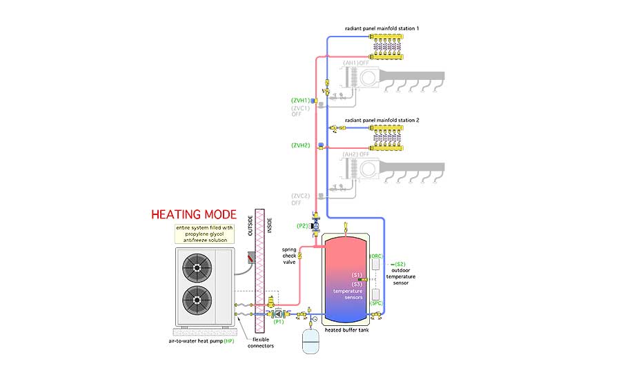
During heating operation, the fluid temperature in the buffer tank is determined by an outdoor reset controller. The maximum target water temperature at the mid-height sensor (S1) in the buffer tank is 110°, corresponding to an outdoor temperature of 0°. The minimum target water temperature at sensor (S1) is 80°, corresponding to an outdoor temperature of 52.5° or higher. Outdoor reset control of the buffer tank temperature allows the system to meet the heating load of the building while maintaining the lowest possible water temperature required of the heat pump. This maximizes its coefficient of performance.
The buffer tank is shown in a “3-pipe” configuration. This allows heated or chilled fluid from the heat pump (when it’s operating) to go directly to the load without first passing through the buffer tank. At the same time it couples the thermal mass of the lower portion of the tank to the heat pump to prevent short cycling. This piping also allows the buffer tank to provide hydraulic separation between the heat-pump circulator (P1) and the load circulator (P2). The piping is optimized to preserve stratification during heating mode operation.
The entire system is filled with a 30% solution of inhibited propylene glycol antifreeze.
We’ll cover cooling mode operation in next month’s Renewable Heating Design column.
To read Siegenthaler’s article: “Renewable Heating Design” in pdf form, please see here.


