
Last month, we covered the concept of combining heat pumps with hydronic distribution systems. We also discussed the specifics of an air-to-water heat pump supplying multiple zones of radiant panel heating. This month we will look at how that same system operates in cooling mode, and discuss specifics on how to configure control.
Chilling out
Figure 1 shows the air-to-water pump system as it would operate in cooling mode. Chilled antifreeze solution from the heat pump or buffer tank is delivered to one or both of the zoned air handlers, while the radiant panel zones remain off.
During cooling operation, the temperature of the buffer tank is maintained between and upper and lower limit by a setpoint controller. A typical temperature range would be between 45° F and 60°.
> Figure 1.
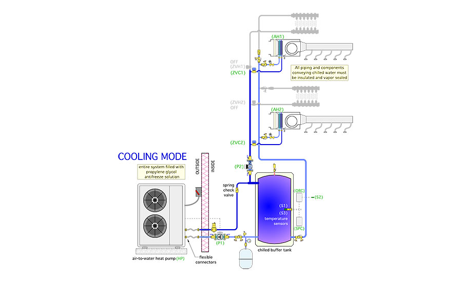
All piping carrying chilled fluid must be insulated and vapor sealed to prevent condensation. Migration of chilled water into the radiant panel zones is prevented by a combination of a closed zone valve on the supply pipe and a check valve on the return side piping.
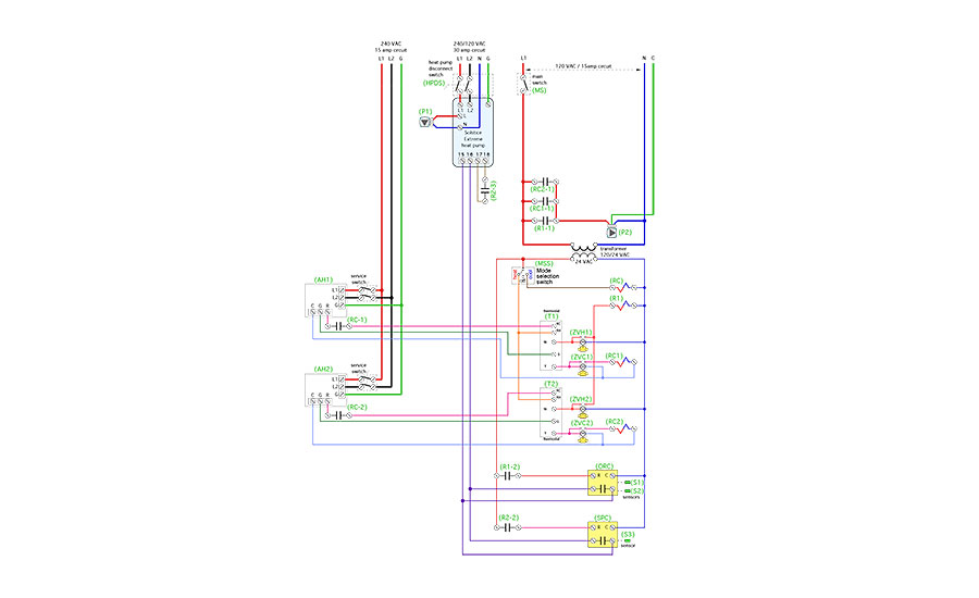
Figure 2 shows one way to wire electrical controls for the system.
The mode selection switch determines if the system operates in heating, cooling or remains off. The temperature in each zone is monitored by a heating/cooling thermostat. In cooling mode the zone thermostats turn on their respective air handlers and open their associated zone valves. The distribution circulator also is turned on. A demand for cooling from either zone also turns on a setpoint controller that operates the heat pump to maintain the buffer tank temperature within a suitable temperature range for cooling.
> Figure 2.
Description of operation
The following is a description of operation for the system. Keep in mind that specific makes and models of heat pumps may require slightly different wiring to enable their operation in heating or cooling modes. Always verify the specific wiring requirements for the heat pump being used and ensure it is coordinated with the balance of system wiring.
Power supply: The heat pump and circulator (P1) are powered by a dedicated 240/120 VAC 30 amp circuit. The heat pump disconnect switch (HPDS) must be closed to provide power to the heat pump. The remainder of the control system is powered by 120 VAC/15 amp circuit. The main switch (MS) must be closed to provide power to the control system. Both fan coils are powered by a dedicated 120 VAC/15 amp circuit. The service switch for each air handler must be closed for that air handler to operate.
Heating mode: The mode selection switch (MSS) must be set for heating. This passes 24 VAC to the RH terminal in each thermostat. Whenever either thermostat demands heat, 24 VAC is passed from the thermostat’s W terminal to the associated zone valve (ZVH1 or ZVH2). When the zone valve reaches its fully open position its internal end switch closes, passing 24 VAC to relay coil (R1). Relay contact (R1-1) closes to pass 120 VAC to circulator (P2). Relay contact (R1-2) closes to pass 24 VAC to outdoor reset controller (ODR).
The (ODR) measures outdoor temperature at sensor (S2) and uses this temperature along with it settings to calculate the target supply water temperature for the buffer tank. It then measures the temperature of the buffer tank at sensor (S1). If the temperature at (S1) is more than 5° below the target temperature, the (ODR) closes its relay contact. This completes a circuit between terminals 15 and 16 in the heat pump, enabling it in heating mode.
After a short time delay the heat pump (HP) turns on circulator (P1) and verifies adequate flow through the heat pump. After a short time delay, the heat pump compressor turns on its compressor. The heat pump continues to operate until the temperature at sensor (S1) is 5° above the target temperature calculated by the (ODR), or neither thermostat calls for heat or the heat pump reaches its internal high limit setting. Note: Neither air handler operates in heating mode, regardless of the fan switch setting on the thermostats.
Cooling mode: The mode selection switch (MSS) must be set for cooling. This passes 24 VAC to relay coil (RC), normally open contacts (RC-1) and (RC-2) close allowing 24 VAC from the air handlers to pass to the associated RC terminal in each thermostat. Whenever either thermostat calls for cooling, 24 VAC is passed from the thermostat’s Y terminal to the associated zone valve (ZVC1, or ZVC2).
When the associated zone valve reaches its fully open position its internal end switch closes, passing 24 VAC to associated relay coil (RC1) or (RC2). Associated relay contacts (RC1-1) or (RC2-1) close to pass 120 VAC to circulator (P2). Associated relay contacts (RC1-2) or (RC2-2) close to pass 24 VAC to the cooling setpoint controller (SPC). The cooling setpoint controller measures the temperature of the buffer tank at sensor (S3). If this temperature is 60° or higher, the (SPC) relay contact closes, completing a circuit between terminals 15 and 16 on the heat pump (HP,) enabling it to operate. Associated relay contacts (RC1-3) or (RC2-3) close between terminals 17 and 18 in the heat pump (HP), for cooling mode. The heat pump (HP) turns on circulator (P1) and verifies adequate flow through the heat pump. After a short time delay, the heat pump compressor turns on its compressor and operates in chiller mode.
This continues until the temperature at sensor (S3) drops to 45°, or until neither zone thermostat calls for cooling, or until the heat pump reaches in internal low limit setting. The blowers in the air handlers can be manually turned on at the thermostats when the mode selection switch (MSS) is set to cooling. The blowers will operate automatically whenever either cooling zone is active.
Pay attention
Low-ambient air-to-water heat pumps can fill a unique niche for heating and cooling of residential and light-commercial buildings. Although their COPs are not necessarily as high as geothermal heat pumps, their installation cost is substantially less. They are cost competitive without subsidies and allow low-temperature radiant panel systems to deliver comfort far superior to forced-air heat pumps.
2019 is going to be a major “rollout” year for air-to-water heat pump systems in North America. Several manufacturers will be introducing new products in this category. They’ve obviously recognized opportunity and chose to pursue it. I highly recommend you also take a look at how air-to-water heat pumps can fit into your comfort offerings.
To read Siegenthaler’s article: “Renewable Heating Design Pt. 2” in pdf form, please see here.
To read Siegenthaler’s article: “Renewable Heating Design Pt. 1” in pdf form, please see here.


