
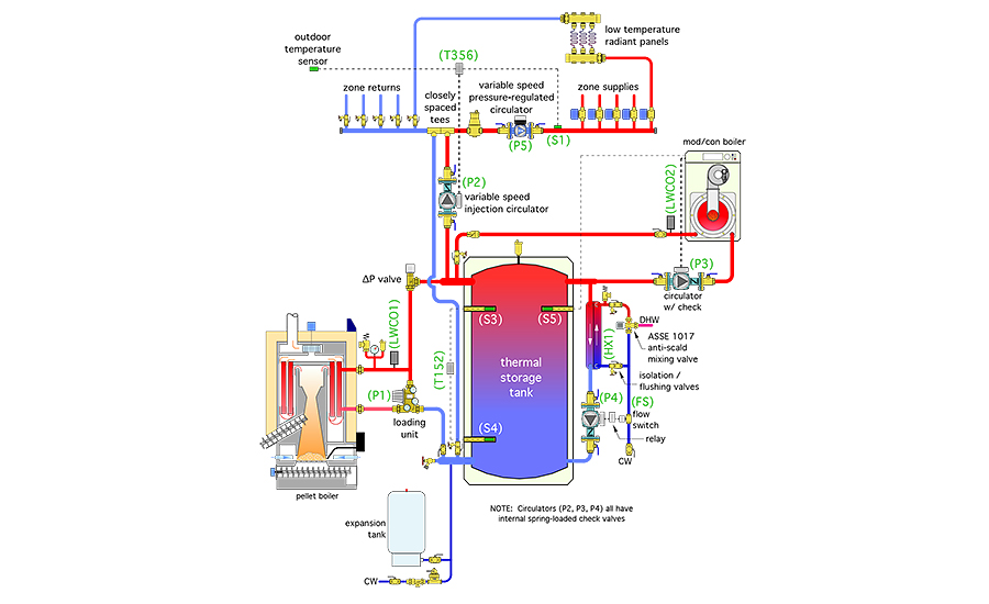
In February’s Renewable Heating Design column, I described a simple yet sophisticated design for a system that supplies space heating and domestic hot water using a pellet boiler as the primary heat source. The piping and electrical schematics for that system are shown in Figures 1 and 2 below.
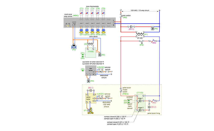
Every hydronic system design should include a piping schematic, electrical control schematic, a description of operation and initial settings for all controllers. The following is a description of operation for the system shown in Figures 1 and 2.
Power supply: 120 VAC power for the pellet boiler is supplied from a dedicated circuit. The service switch for the pellet boiler must be closed and the low-water cutoff (LWCO1) must detect water for the pellet boiler to operate.
120 VAC power for the auxiliary boiler is supplied from a dedicated circuit. The service switch for the auxiliary boiler must be closed and the low water cutoff (LWCO2) must detect water for the auxiliary boiler to operate.
Power for the circulators (P2) (P4) and (P5), the 24-VAC transformer (X1), the multi-zone relay center (MZRC), temperature controller (T152) and relay coil (R2) is supplied through another 120-VAC dedicated circuit. The main switch (MS) must be closed for these devices to operate.
Pellet boiler operation: The pellet boiler enable switch (PBES) must be closed for the pellet boiler to operate. Whenever sensor (S3) in the upper portion of the thermal storage tanks is below 128º F the stage 1 contacts in the (T152) controller close. This passes 24 VAC from transformer (X1) to relay coil (R2). Relay contact (R2-1) closes across the external demand terminal of the pellet boiler. The pellet boiler turns on circulator (P1) and initiates its startup routine. Relay contact (R2-2) also closes. 24 VAC passes through the closed stage 2 contacts of controller (T152) and through the closed contacts (R2-2) to provide another path for 24 VAC to relay coil (R2). When the temperature at the upper tank sensor (S3) reaches 132º the stage 1 contacts in the outdoor reset controller (T152) open. However, 24 VAC continues to pass through the closed stage 2 contacts in controller (T152) and closed contacts (R2-2) until the lower tank sensor (S4) reaches 175º. At that point the stage 2 contact in controller (T152) opens, breaking 24 VAC to relay coil (R2), which removes the external demand from the pellet boiler, allowing it to follow its normal shutdown procedure.
Auxiliary boiler operation: The internal controller within the auxiliary boiler monitors the temperature at sensor (S5) in the upper portion of the thermal-storage tank. If that temperature drops to or below 125º, the auxiliary boiler turns on, along with its associated circulator (P3). Heated water is directed from the auxiliary boiler to the upper left header of the thermal storage tank. From there it can either flow to the load through circulator (P2) if a heating zone is active, or through the upper portion of the thermal storage tank. When the temperature at sensor (S5) reaches 135º, the auxiliary boiler and circulator (P3) are turned off.
 Space heating distribution system operation: Upon a call for heating from any zone thermostat (T1, T2, T3, T4, T5), the associated zone valve (ZV1, ZV2, ZV3, ZV4, ZV5) is turned by the multi-zone relay center (MZRC). Circulator (P5) is turned on and operates in a preset constant differential pressure mode. 120 VAC also is passed to transformer (X2), which provides 24 VAC to the (T356) variable-speed injection controller. The (T356) controller boots up and measures the current outdoor temperature. It uses that temperature along with its settings to calculate a target supply water temperature for the distribution system. The (T356) then controls the speed of circulator (P2) to inject hot water from the upper left header of the thermal storage tank into the distribution system at the closely-spaced tees. The rate of hot water injection varies in an attempt to hold the supply water temperature measured at sensor (S1) as close to the target temperature as possible. This operation continues as long as one or more zones remain active. When all zone thermostats are satisfied, the (MZRC) turns of circulator (P5), transformer (X2) and the injection mixing controller (T356).
Domestic water heating: The temperature of the upper portion of the thermal storage tank is continuously maintained at or above 125º by either the pellet boiler or auxiliary boiler. Whenever there is a demand for domestic hot water of 0.6 gpm or higher, flow switch (FS) closes, passing 24 VAC to the coil of relay (R3). Relay contact (R3-1) closes to turn on circulator (P4) which immediately routes hot water from the top of the thermal storage tank through the primary side of stainless steel heat exchanger (HX1). Cold domestic water passes in counterflow through the other side of heat exchanger (HX1) and is fully heated to or above the desired domestic hot water delivery temperature of 115º. The hot water leaving (HX1) passes through an ASSE 1017-listed anti-scaled mixing valve to ensure that the maximum hot water delivery temperature to the plumbing system is 115º. When the domestic hot water flow rate drops to 0.4 gpm or less the flow switch (FS) opens, turning off relay coil (R3) and circulator (P4).
Suggested initial controller settings
- Stage 1 contacts in (T152) controller: contacts close at 128º, open at 132º; Stage 2 contacts in (T152) controller: contact close at 165º, open at 175º;
- Injection mixing controller (T356) settings: No load condition: 70º supply water temperature when outdoor temperature is 70º. Design load condition: 110º supply water temperature when outdoor temperature is 0º or lower;
- Circulator (P5) setting: Differential pressure constant at the required Delta-P with all zone valves open;
- Auxiliary boiler setting: Boiler on when temperature at sensor (S5) is 125º or lower; Boiler off when temperature at sensor (S5) is 135º or higher;
- Pellet boiler settings: High limit temperature = 200º; Other setting as per boiler manufacturer’s recommendations; and anti-scald mixing valve setting: 115º domestic hot water leaving temperature.
That’s a fairly detailed description of a system with a lot of synergistic attributes. I’ll leave it to pme readers to finalize these concepts for their own system needs and in doing so, pushing the envelope on “sustainable” use of renewable thermal energy.

