Last month, we began with a concept for an “ideal” thermal storage tank. This tank was then shown in both a classic four-pipe configuration, as well as a newer configuration called two-pipe. This month, we’ll look at a morphing of these two piping methods to create a three-pipe configuration. We’ll also look at options for connecting multiple thermal storage tanks together.
Three-pipe configuration: What do you get when you “average” a four-pipe tank with a two-pipe tank? You guessed it: A three-pipe tank, as shown in Figure 5.
This piping configuration is well suited for systems using heat pumps as the heat source. These systems typically have higher flow rates relative to systems with biomass boilers. The tank functions more as a “buffer” rather than providing hours of thermal storage capacity, as it would in a biomass boiler or solar-thermal application. Higher flow rates from the heat pump, if allowed to enter the tank, tend to cause mixing, which elevates the return water temperature to the heat pump, lowering its COP.
> FIGURE 5.
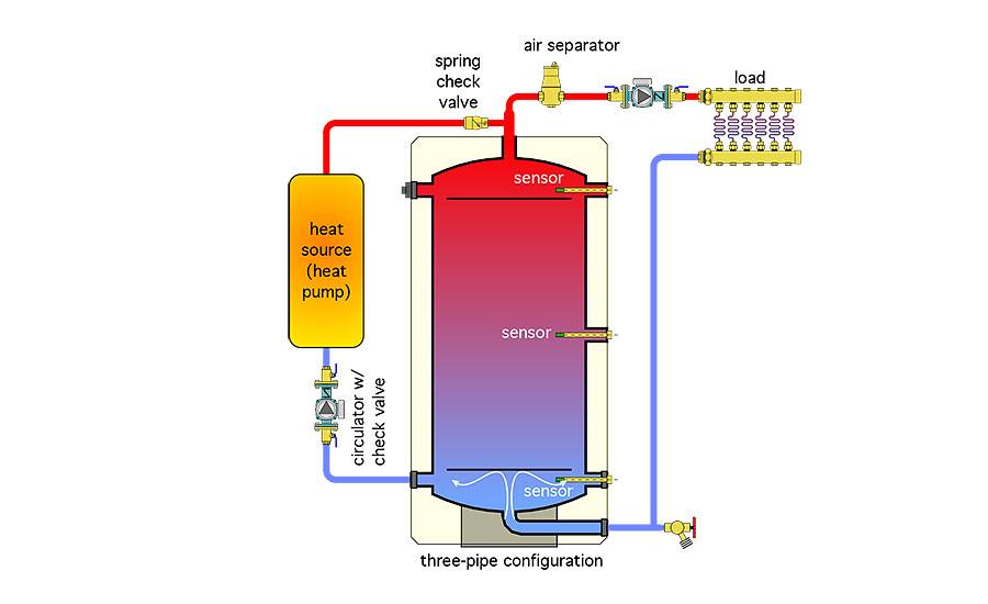
This configuration allows for direct-to-load flow on the supply side of the system — one of the stated advantages of the two-pipe tank setup. But it also engages the tank’s thermal mass on the return side of the load.
Because flow returning from the load passes through the tank, it is not necessary to use a ∆P valve in the heat source circuit. However, a spring-loaded check valve should still be installed to prevent reverse thermosiphoning from the tank through the heat source when it’s off. The spring check could be a cartridge within the heat source circulator, or a separate check valve near the upper tank header, or both.
The performance of systems piped very similar to Figure 5 was simulated using TRNSYS modeling software. The heat source was a geothermal water-to-water heat pump. The simulation showed a significant (about 10%) increase in the heat pump’s average COP relative to a classic four-pipe buffer tank configuration. The performance gain was attributable to reduced mixing within the tank, allowing the coolest water to be returned to the heat pump’s condenser. You can get more information on this simulation at this website: tinyurl.com/y556dfz3.
Multiple tank arrays: In situations where high thermal storage volume is needed, multiple smaller tanks can be piped in “arrays” using variations of these single-tank scenarios. One such configuration is shown in Figure 6 on Page 11.
> FIGURE 6.
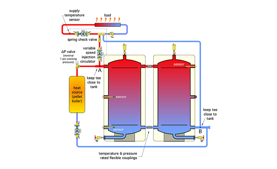
This configuration is also well-suited to systems using pellet boilers that need long burn cycles (average of three run hours per start), and are fired independently of the load based on changes in tank temperature.
This layout is a variation of the two-pipe design shown in Figure 4B in last month’s column. It allows direct-to-load piping on the supply side. The load risers connect to closely spaced tees in the distribution system, allowing heat transfer to the distribution to be under the control of a variable-speed injection circulator.
The tanks in Figure 6 on Page 11 are “closely coupled.” A pressure- and temperature-rated flexible coupling is used to couple short headers on the side connection. Figure 7 on Page 11 shows a detail of this coupling and the adjacent piping.
> FIGURE 7.
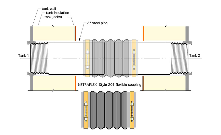
The flexible couplings allow for slight deviations in the alignment of the tank connections, such as those that might be caused by a floor slab that’s not perfectly flat.
Keeping the tanks close together results in minimal head loss between point B in the lower right tank header, and point A in the upper left tank header. The two tanks act almost as if they were a single, larger tank, and thus maintain good hydraulic separation between the heat source circulator and the variable-speed injection circulator. A ∆P valve is used to prevent unintentional flow migration through the heat source when it and its associated circulator are off.
Any ports not used for piping connections could be used for sensor wells, or simply plugged and insulated.
This piping concept can be used to connect additional tanks. However, keep in mind that multiple smaller tanks often create significantly more heat loss compared to a single, larger tank, due to a much higher surface area to volume ratio.
Three’s a charm: Another multi-tank configuration that would be well-suited to pellet boiler applications is shown in Figure 8 on Page 12.
> FIGURE 8.
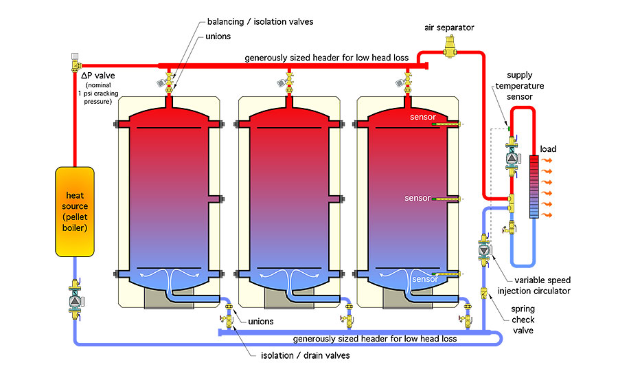
This array is another variation of the two-pipe concept. It allows direct-to-load heat flow on the supply side. It also leverages the presence of a top and bottom connection on each tank.
The three tanks are piped in reverse return using low-loss headers. This helps equalize flow rates through each tank. A balancing valve that can also serve as an isolation valve allows these flow rates to be fine-tuned. A combination isolation/drain valve is installed at the lower connection on each tank.
Unions are shown at each tank piping connection. These unions, in combination with the valves, allow each tank to be fully isolated from, or removed from, the system if ever necessary. However, the logistics associated with potentially removing or replacing a tank in a multiple tank array require careful placement of the tanks and the piping. The goal is to allow isolation and removal of any tank without disturbing any adjacent piping or shutting down the system.
The tank array interfaces to the distribution system using closely spaced tees and a variable-speed injection circulator. A central air separator is shown at the high point of the tank array. It vents air from the tanks during filling and provides continuous microbubble separation for the system.
A ∆P valve is again used to prevent flow migration through the heat source when it’s off. This valve also prevents reverse thermosiphoning from the tank through the heat source, eliminating the need for a check valve. A spring check valve is used on the load side of the tank array to prevent forward thermosiphoning. This configuration provides many possibilities for sensor mounting.
More possibilities: There are several other ways in which one or more thermal storage tanks having the connections shown in Figure 1 in last month’s column could be piped. The best configurations will encourage temperature stratification within the tank(s). They will also provide hydraulic separation between circulators, expedite air removal at high points, provide low point drainage, prevent forward or reverse thermosiphoning and maintain as much control over heat transfer as possible.
To read Siegenthaler’s article: “Piping permutations — Part 1” in pdf form, please see here.
To read Siegenthaler’s article: “Piping permutations — Part 2” in pdf form, please see here.


