
During four decades of dealing with hydronic systems, I’ve confirmed two characteristics that always govern their operation. Both are rooted in the tenants of thermodynamics. Neither should be thought of as mysterious. When understood and respected, these behaviors unfailingly reveal why a given system does what it does. This knowledge can be a real asset for designing as well as troubleshooting hydronic systems.
Absolutes
Fundamentally, there are two things that every hydronic system you’ll ever design, install or troubleshoot “tries” to do. They all try to operate at conditions in which energy input equals energy output. This applies to both mechanical and thermal energy inputs and outputs. I call these states thermal equilibrium and hydraulic equilibrium.
Thermal Equilibrium is a condition at which the rate of heat input to the water from the heat source (boiler, heat pump, solar collector array, whatever...) is exactly the same as the rate of heat release from the heat emitters, and to a lesser degree piping, valves and other components through which the heated water passes.
The supply water temperature and temperature drop the system tries to stabilize at are always those necessary to balance these rates of heat transfer. In some situations, these temperatures can be significantly higher or lower than what might be expected based on controller settings. They might be such that the system delivers heat exactly as intended, or such that operation of the system is very unsafe. Thermodynamics “doesn’t care” about controller settings, comfort, or safety, it only “cares” about finding a balance between energy input and output.
Consider the system in Figure 1. The heat source — whatever it is — delivers heat to the circulating water at 50,000 Btu/h. The distribution system is a series loop with 154 feet of residential fin-tube baseboard. The high limit controller on the heat source is set to turn it off if and when the water temperature leaving the heat source reaches 200° F.
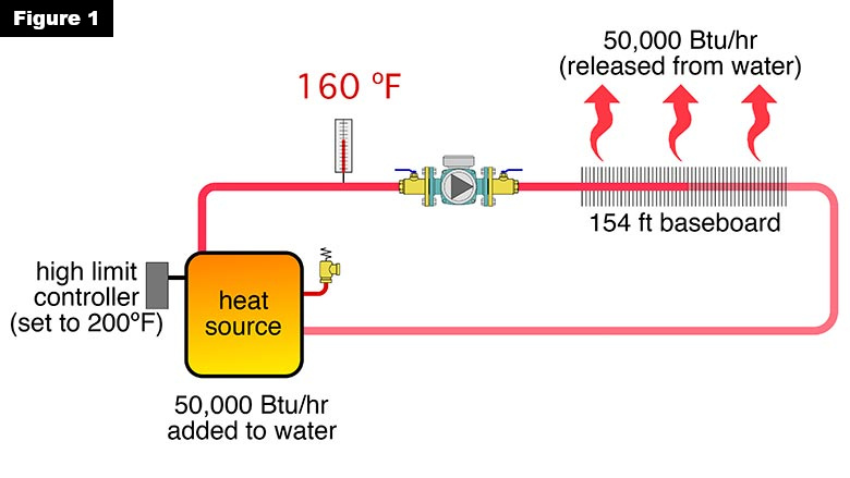
When the system is put into operation, the water leaving the heat source steadily climbs to 160° F, and stabilizes at that temperature. The system has reached thermal equilibrium at that condition. The 50,000 Btu/h being added to the circulating water by the heat source is being dissipated from the water as it passes through the 154 feet of baseboard.
160° F is 40° F lower than the temperature setting of the controller operating the heat source. Some might see such a condition as an “obviously” defective controller. It’s not. Even if the high limit controller was set for 250° F, the supply water temperature in this system would not climb above 160° F. There’s no thermodynamic “need” for the temperature to climb any higher because the rate of heat dissipation by the distribution system is balanced with the rate of heat input by the heat source. This also demonstrates that the high-limit controller on a heat source isn’t necessarily “in charge” of the system’s water temperature. Instead, it is there to prevent an over-temperature condition if and when such a condition might occur.
The concept of thermal equilibrium is a powerful guide for those designing hydronic heating systems. The design objective is to ensure that thermal equilibrium is established at conditions that provide excellent comfort, and do not adversely affect the operation, safety or longevity of the system’s components.
Flow fundamentals
There’s another form of energy being put into and dissipated from the fluid in hydronic systems as they operate. It’s mechanical energy called “head.” An operating circulator converts electrical energy into head energy and imparts it to the fluid.
At the same time, every component through which flow passes dissipates head energy because of friction between water molecules, and between those molecules and the surfaces of the components they pass through.
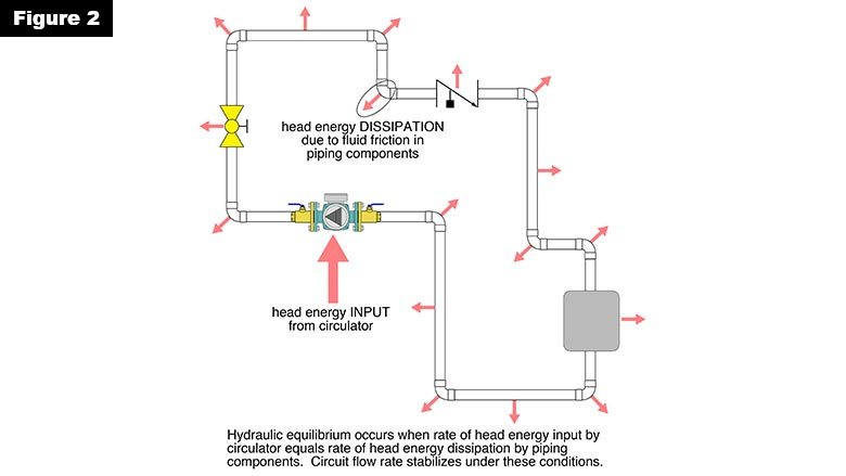
All hydronic circuits will stabilize at a flow rate where the rate of head energy input exactly matches the rate of head energy dissipation. This is hydraulic equilibrium, and it is usually achieved within a few seconds of turning on the circulator. The concept of hydraulic equilibrium is illustrated in Figure 2.
The system remains in hydraulic equilibrium until the system curve or pump curve changes. The system curve would change due to a valve adjustment, a zone valve opening or closing, and to a lesser extent by changes in fluid’s density and viscosity as it warms up or cools down. The pump curve changes if the circulator changes speed. When and if such changes occur, the system quickly settles to a new flow rate where head energy input from the circulator matches head energy loss from the currently configured piping system.
You can predict the condition at which hydraulic equilibrium will occur. It’s done by first constructing a head loss curve for the circuit, and then overlaying it with the pump curve of a circulator used in the system. An example is shown in Figure 3.
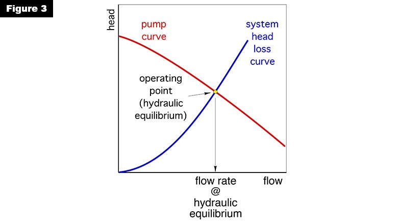
The point where these curves cross is called the operating point and is the only possible condition where head input exactly balances head dissipation. In other words, this is the point where hydraulic equilibrium occurs.
You’ve heard that “nature likes a balance.” This is perfectly illustrated through thermal and hydraulic equilibrium in all hydronic systems. Our task as designers is to also ensure the system delivers the desired comfort, operates efficiently and safely while operating at both thermal and hydraulic equilibrium. When you ponder the operation of your systems from these standpoints it all just makes sense.


