The market for pellet-fueled “biomass” boilers continues to grow in North America. This market expansion is driven by several factors.
- The volatile price of fuel oil and propane, which are commonly used in rural and semi-rural buildings where wood-based heating is more common. The cost of heat delivered from wood pellets remains lower than heat supplied from fuel oil or propane, especially in the northeastern United States. For example, based on recent NYSERDA fuel price data for upstate New York, the cost of 1 million Btu (1 MMBtu) of delivered heat would be $29.86 for propane burned at 92% efficiency, $25.34 for No. 2 fuel oil burned at 85% efficiency, and $20.33 for wood pellet burned at 75% efficiency.
- The use of indigenous energy sources (such as wood) keeps money spent on heating fuel within local economies rather than spreading it across providences or out of the country.
- Burning wood for heating is generally considered to be carbon neutral. The carbon released during combustion is essentially equivalent to the carbon that would be released if the tree from which the wood came died and decayed in the forest.
In short, the use of wood in high-efficiency/ low emissions heat sources offer benefits that appeal to consumers, politicians and environmentalists.
Getting it right: Modern biomass boilers are as different from earlier generation wood-burning boilers as smartphones are from their rotary dial predecessors. For example, some modern pellet-fired boilers can operate unattended for weeks. They automatically convey pellets from bulk storage to their combustion chamber, ignite them, and modulate the combustion process based on water temperature and the oxygen content of the exhaust gases. Some even compress the small amount of ash produced, which lengthens the time between cleanings. When the ash drawer needs to be emptied, the boiler sends a notice to the owner’s smartphone.
The average heating contractor might assume that a pellet-fired boiler can be treated like any other boiler. In a retrofit application, they might assume that a pellet-fired boiler is just a new “box” that gets placed next to the existing boiler and piped into the system. Their understanding of how both boilers should work might be follows: The pellet-fired boiler supplies the load when it’s operating, and automatically transfers the load to the conventional boiler if it runs out of fuel or can’t keep up with the load. Although this seems logical, and is partially true in some systems, it is an oversimplified view. It overlooks several unique operating requirements of pellet-fired boilers that must be respected if peak performance is to be realized.
To achieve high thermal efficiency, low emissions and unsurpassed comfort, all pellet-fired boilers must be combined with an appropriately designed “balance-of-system.” This refers to all aspects of the complete heating system other than the biomass boiler.
One of the major components in the balance-of-system is a properly sized and piped thermal storage tank. Other important components and subsystems include properly configured controls, high-efficiency circulators, mixing valves and low-temperature heat emitters. If any of these components or subsystems are improperly selected or installed, it’s likely the pellet-fired boiler will not perform up to its potential. This will be reflected through increased fuel consumption, higher emissions and compromised comfort. Although the boiler often gets blamed for poor system performance, it’s typically not the root cause of most operational problems.
They’re different: Pellet-fired boilers take considerably longer to come “online” following a call for heat compared to a conventional boiler. Even small pellet boilers often need 10-15 minutes from when they are called to operated until they are ready to deliver heat to the system. During that time, they go through stages such as flushing the combustion chamber of any residual pyrolytic gases, automated ash cleaning, loading pellets, igniting the pellets, stabilizing the combustion for optimal air/fuel ratio and warming the boiler’s heat exchanger above the dewpoint of the exhaust gases.
This longer startup time, and the desire to keep the pellet-fired boiler operating at or close to steady state conditions over as much of the operating cycle as possible, point to the need for fewer and longer operating cycles. Think in terms of hundreds of on/off cycles over the course of a heating season, rather than thousands of cycles, which often occur with fossil-fueled boilers.
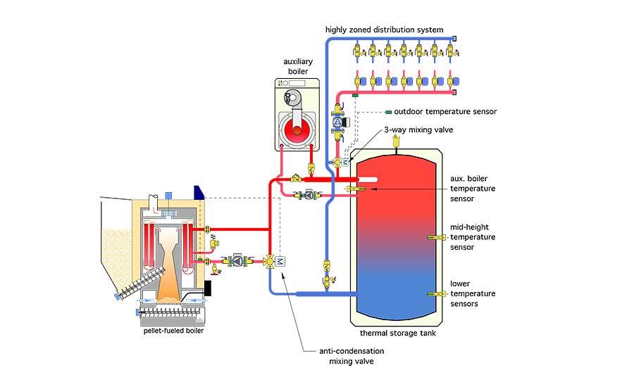
The best way to achieve long and stable operating cycles is to include water-based thermal storage in the system. Figure 1 shows one way to do this using a single thermal storage tank to buffer both the pellet-fired boiler and the auxiliary boiler.
Notice that the thermal storage tank is piped differently than in other systems using buffer tanks. This is a “2-pipe” tank configuration. The load is piped in between the boilers and the thermal storage tank. This configuration allows the possibility of heat flow directly from either boiler to the load without first passing through the thermal storage tank. It also reduces flow velocity into the tank when the load and pellet boiler are operating simultaneously. This helps preserve temperature stratification within the tank.
The 3-way motorized mixing valve to the right of the pellet-fired boiler modulates to keep the inlet water temperature to the boiler above the dewpoint of the flue gases, and thus protect the pellet-fired boiler from sustained flue-gas condensation. This valve is usually controlled by the pellet-fired boiler.

Figure 1.
The other 3-way motorized mixing valve, seen just below the distribution circulator, operates based on outdoor reset control to provide the ideal supply water temperature to the distribution system.

Figure 2.The cost of heat delivered from wood pellets remains lower than heat supplied from fuel oil or propane, especially in the northeastern United State.
The auxiliary boiler is piped into the upper portion of the storage tank. This provides adequate buffering against a highly zoned distribution system, but, thanks to temperature stratification, doesn’t require the auxiliary boiler to heat the entire thermal storage tank.
The temperature sensors mounted at different heights within the tank allow for “temperature stacking.” This is a control technique that is already programmed into the controls of some modern pellet-fired boilers. During a demand for heating, this control technique turns on the boiler before hot water is fully depleted from the tank.
It also keeps the pellet-fired boiler operating until a relatively high temperature is achieved at the lower temperature sensor location. Once the tank is fully “charged” with high-temperature water, it’s likely that the boiler can stay off, in some cases for several hours. Over the course of a heating season, this control technique provides fewer but longer operating cycles, which improves seasonal efficiency and reduces emissions.
These piping and control details are “complementary” to the operating characteristics of the pellet-fueled boiler and the distribution system. They allow heated water to supply the load while the pellet-fired boiler is warming up. At times, they also allow a small zone to be supplied from the buffer tank without having to fire the pellet-fueled boiler. The distribution system can accept heat from either boiler, or both boilers operating simultaneously when necessary, with no compromise in comfort.
How much storage? Opinions vary on how much water-based thermal storage is required in systems with pellet-fired boilers.
Some manufacturers make a broad claim that, because their boilers modulate, no thermal storage is required. Given that short cycling has been observed with mod/con boilers having 5:1 or higher turndown ratios (versus the more limited 3:1 turndown ratio of most pellet-fired boilers), this claim seems dubious, especially for highly zoned systems. Extensive pellet boiler testing at Brookhaven Laboratories also has shown a marked reduction in cycling when thermal storage is included in the system.
However, one could argue that a large heated floor slab provides immense thermal mass, even when compared to several-hundred gallons of water. I would agree. We recently made this comparison for a 6,000-square-foot heated concrete slab that was 8 inches thick. That slab has more than 60 times the thermal mass of the 210-gallon thermal storage tank being considered for the project.
This issue will surely be studied in more detail. In the meantime, I suggest designers provide between 1 and 2 gallons of water-based thermal storage per 1,000 Btu/h of rated output capacity, for both pellet- and chip-fired boilers.
The upper end of this sizing range (2 gallons per 1,000 Btu/h) is appropriate when the system has several independently controlled zones of low-mass heat emitters and/or the boiler has limited or no modulation ability.
The lower end of the sizing range (1 gallon per 1,000 Btu/h) is appropriate when the system uses high thermal mass heat emitters and only one or two zones.
In all cases, be sure the thermal storage tank is very well insulated. I suggest a minimum of R-24 (ºF•hr•ft2/Btu) insulation on all surfaces.
Piping details matter: Getting optimal performance from a thermal storage tank supplied from a pellet-fired boiler requires more than just calculating the tank’s volume and selecting a readily available product of the required volume. A tank with the wrong piping connections will not stratify properly. This reduces the usefulness heat available from the tank.
I’ve witnessed this in several systems involving tanks that cost several thousands of dollars. One example is shown in Figure 2.
The piping seen in the lower right of this photo carries the flow returning from the heating distribution system in a large institutional building into the tank. It passes under the tank and enters vertically into the bottom-center connection. This creates a vertical flow jet within the tank that essentially destroys desirable temperature stratification. This has been verified through system monitoring. This sub-optimal performance is both unfortunate and avoidable.
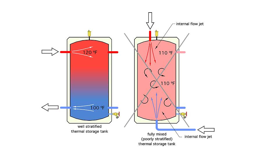
Figure 3 shows a well-stratified thermal storage tank, as well as a tank with strong internal mixing currents.

Figure 3.
Designers should avoid piping that creates any type of vertical flow jet within thermal storage tanks. Instead, piping connections should allow gentle horizontal flow at all entry locations. Hot water should enter and leave from the upper portion of the tank. Cooler water should enter and leave from the lower portion of the tank.
The use of a properly sized and piped thermal storage tank is essential in achieving peak performance from pellet-fired boilers. Modern hydronics technology provides a “media,” which can be cleverly manipulated to accommodate and even complement the unique operating characteristic of these boilers.


