
Many renewable energy systems have thermal storage tanks that bridge the gap between when energy is available from the heating source, and when that energy is needed by a heating load.
In some systems the renewable energy heat source may be a heat pump (water-to-water geothermal source or air-to-water). That heat pump can supply heat for space heating or domestic hot water, as well as chilled water for space cooling.
When the system is zoned for both heating and cooling, the buffer tank will likely be used in both modes of operation.
In climates where there’s a significant “dead band” between the end of the heating season and the beginning of the cooling season, and vice versa, it’s possible to use a single buffer tank for both heating and cooling modes. The tank would cool to surrounding space temperature over several days at the end of the heating season, but well before it would need to be chilled for cooling. The tank’s temperature would also rise to surrounding air temperature over several days between the end of the cooling season and the beginning of the heating season.
Still, there may be times when it’s desirable to provide warm water for space heating while the buffer tank is still relatively cool from a recent call for cooling. An example would be when a strong cold front passes through the area, dropping outdoor air temperatures from the 80s into the 60s in a matter of a few hours. The opposite is also possible when a particularly warm or humid day comes along in early May, before the cooling season has started in a northern U.S. location.
Switching a single buffer tank system quickly between operating modes can waste energy, and delay delivery of water at the required temperature to the load. It would be better if the buffer tank could be temporarily bypassed during such times.
There are several possible ways to create systems that bypass the buffer tank. This month, we’ll discuss one approach that’s particularly appropriate when the system uses a heat pump for heating and cooling, along with a boiler for supplemental heating.
Forks in the road
Figure 1 shows the piping schematic for the system while operating in heating mode.
> Figure 1
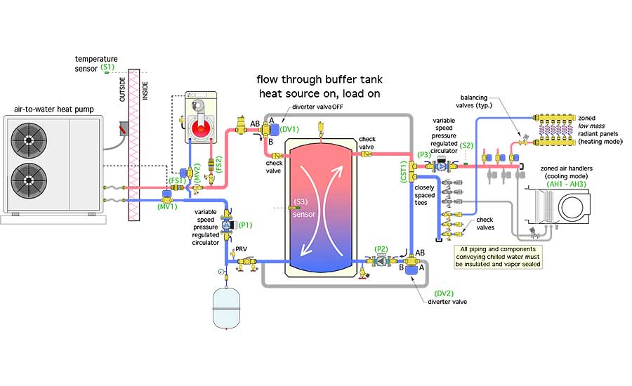 This system uses two motorized three-way ball valves for flow diversion. The actuators driving those valves are spring-return. When supplied with power (which can be either 24VAC or line voltage) each actuator turns its valve so that flow entering the “AB” port passes out through the “A” port. This allows flow from either heat source to completely bypass the buffer tank. It also allows flow returning from the load to completely bypass the tank.
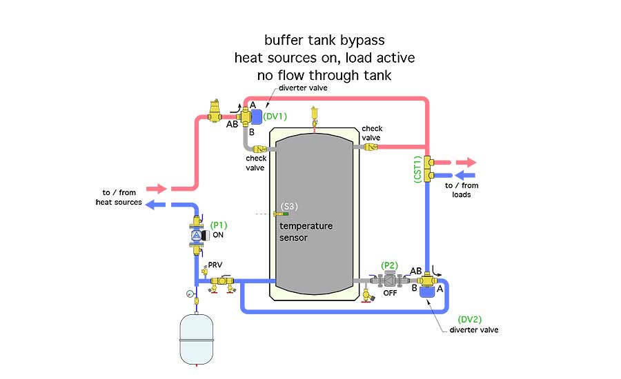
When power is removed from the actuators, a spring within each actuator returns the diverter valves to a position that allows flow entering the “AB” ports to pass out through the “B” port. This allows both supply and return side flows to pass through the buffer tank. Thus, a simple on/off electrical signal can be used to route flow through or around the buffer tank. Figure 2 shows the tank bypass mode.
> Figure 2
The time required for the diverter valves to move between their two end positions varies with the actuator used. Typical time for “fast” actuators is a few seconds (3-6). Slower actuators can take 60-90 seconds to drive the valve stem through its full 90-degree rotation. The faster actuators would be preferred in this application.
In Figure 1, at least one of the heat sources is on, and at least one of the heating zones is on. All three circulators (P1, P2 and P3) are operating. The buffer tank provides hydraulic separation between (P1) and (P2), while the closely spaced tees (CST1) provide hydraulic separation between (P3) and the other circulators. Heat is entering the left side of the buffer tank as heat is extracted from the right side of the tank.
The spring-loaded check valves in the upper tank headers prevent flow from short-circuiting through the tank in certain modes. They also prevent buoyancy-induced thermosiphoning from the tank through external piping when the circulators are off.
The distribution system shown uses a variable-speed pressure-regulated circulator to create flow in both heating and cooling modes. Three-zone valves supply three low-thermal mass radiant panels for heating. Another three-zone valve supplies three air handlers for cooling. Each distribution circuit supplied by the header includes a flow-balancing valve. Check valves are used on the return side of each zone circuit to prevent migration of heated or chilled water into inactive piping. These are especially important given that this system can switch quickly between heating and cooling modes when necessary.
It would be possible to use other heat emitters or cooling terminal units in this system. For example, all the heat emitters could be air handlers, which have condensate drip pans and thus could be used for cooling. Keep in mind that this system has the ability to quickly change from heating to cooling mode. A high-thermal mass heat emitter, such as a heated slab, is not going to cooperate with this quick changeover objective. If radiant panel heating is used, the panel(s) should have low thermal mass.
Flow through the heat pump and boiler is provided by a single variable-speed pressure-regulated circulator (P1). The heat pump and boiler are both equipped with a motorized ball valve (MV1 and MV2), or a zone valve with a high Cv that opens when the associated heat source is on, and closes, by spring return actuator, when that heat source is off. This prevents any inadvertent flow between the buffer tank and either heat source, when they are off, due to the slight pressure differential created by circulator (P2) when it’s on.
The variable-speed circulator (P1) is set to produce a constant differential pressure sufficient to create design flow through both the heat pump and boiler if they are operating simultaneously. Individual flow rates through the heat pump and boiler can be set using balancing valves or with pressure-independent flow regulators. The speed of circulator (P1) reduces when only one heat source is operating. This lowers electrical energy use.
Both heat sources pass their flow either into the buffer tank (if the diverter valves are off) or around the buffer tank (if the diverter valves are on). Ultimately that flow ends up at another set of closely spaced tees (CST1) where it’s handed off to variable-speed circulator (P3). The closely spaced tees provide hydraulic separation between circulator (P3) and the other circulators in the system.
If an air-to-water heat pump is used in a cold-climate application, the entire system would operate with an appropriate concentration of antifreeze.
Do this, do that
The control logic to operate this system is based on a few basic concepts:
-
The operating mode (e.g., heating or cooling) of the system is set by a master thermostat. All other thermostats would have to operate in the mode set on the master thermostat.
-
The heat pump would be controlled for first-stage heat input. The mod/con boiler would operate for stage-two heat input. If the heat pump was not operating, the boiler would provide full heating backup capacity.
-
A call from any zone would open the associated zone valve and turn on circulator (P3), which would operate in constant differential pressure mode.
-
When the master thermostat is set for heating and a call comes from any heating zone thermostat, the control system first assesses the ability of the buffer tank to supply the load based on the temperature at sensor (S3). The criteria for the “target” temperature at (S3) could be a setpoint or determined based on outdoor reset. If the buffer tank is warm enough to supply the load, circulator (P2) turns on. Flow is routed upward through the tank and over to the closely spaced tees (CST1), where the heated water is handed over to circulator (P3). Neither heat source would turn on. Figure 3 shows the flows involved in this mode.
> Figure 3

If the tank temperature is too low to satisfy the load, the heat pump, motorized valve (MV1) and circulator (P1) turn on as stage-one heat input. The diverter valves would be on, allowing flow to bypass the buffer tank and go directly to the distribution system. If the temperature at sensor (S2) is not approaching the target value at a reasonable rate (determined by PID control logic) the boiler and motorized ball valve (MV2) turn on for supplemental heat input.
The system continues to operate in this manner until either:
A. The supply water temperature at sensor (S2) is some reasonable differential above the target supply temperature.
B. No thermostats are calling for heating.
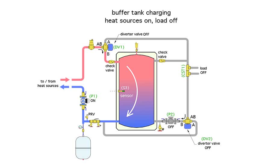
At that point, the diverter valves would be turned off to route flow from the heat source(s) through the buffer tank. Circulator (P3) would also turn off. The heat pump would remain on, while the boiler may or may not remain on, depending on the response from sensor (S3). The objective would be to restore the buffer tank to a temperature a few degrees above the target supply water temperature, parking heat in the tank to be dispatched on the next call from a heating zone. This “tank charging” mode also lengthens the on-cycle of the heat source(s) to minimize potential short cycling. Figure 4 shows the flows in this mode.
> Figure 4
Diverter vs. modulator: If the buffer tank was very cool relative to the target supply heating temperature, and a heating load is active, the diverter valves may have to cycle in order to maintain the supply water temperature to the load in a reasonable range while that tank is also making its way up to a nominal operating temperature. That’s why diverter valves with relatively fast actuators are preferred.
A more sophisticated approach would use modulating three-way valves rather than diverter valves to proportion the flow rates that bypass as well as pass through the tank. The same piping arrangement would work. The valve modulation would be based on the priority of holding the supply water temperature at sensor (S2) close to a target value when a heating load is active, while also routing any surplus capacity into the buffer tank.
Quick switch
If the master thermostat was turned from heating to cooling, and the tank was warm, the diverter valves would route chilled water from the heat pump around the tank. Once the chilled supply temperature at sensor (S2) was a few degrees lower than the target cooling temperature, the diverter valves would turn off to route chilled water into the buffer tank. This chilled water storage mode would continue, provided at least one cooling zone remains active, until the tank temperature is a small differential below the target chilled water supply temperature. This mode of operation could also use modulating valves rather than diverting valves to maintain a reasonable chilled water temperature at sensor (S2), while sending surplus cooling capacity into the buffer tank.
As needed
The system we’ve discussed, like most hydronic systems, can be modified to suit the exact requirements of a project. For example, the air-to-water heat pump could be changed to a geothermal water-to-water heat pump. The distribution system could be changed to zone circulators rather than zone valves and a single variable-speed circulator. Different types of heat emitters and cooling terminal units, such as chilled beams, could be integrated. Multiple single-function controllers combined with hard-wired relays could be replaced by a single programmable controller that handles all the operating logic.
Perhaps you will have a future project that can use the concepts discussed as a starting point for system design?
To read Siegenthaler’s article: “Details for bypassing thermal storage” in pdf form, please see here.

