
For decades, fossil-fueled boilers have dominated the market for hydronic heat sources. There have been several successful, and progressively improved approaches for using a single boiler to supply all space heating and domestic hot water requirements of a building. Millions of such systems exist around the globe, and many fine products are available to support boiler-based hydronic heating systems.
But there’s a missing link which has long served as the “Achilles heel” of hydronics technology: When it comes to cooling, boilers are of no use. Most consumers don’t want to hear that a completely separate system needs to be installed if whole-building cooling is desired. There’s no doubt that the lack of cooling ability has scuttled many decisions to use hydronic heating, even when the latter was deemed the superior comfort choice.
Enter heat pumps
Geothermal water-to-water heat pumps and modern “low ambient” air-to-water heat pumps provide a palatable solution to this situation. Both can provide water at temperatures suitable for several contemporary heat emitters. Both can operate in cold climates. Neither requires on-site fossil fuel, flue dampers, condensate neutralizers, combustion air or venting, and both can provide chilled water for hydronic-based cooling. Moreover, almost every government agency that deals with energy — and every utility — is hard at work promoting the virtues of “beneficial electrification.” There are now hundreds of programs offering financial incentives to install electrically-powered heat pumps.
This trend is worldwide. In July 2020, the Japanese HVAC publication JARN reported the pace of air-to-water heat pump adoption, globally, in 2019, increased at an annualized rate of 25.8%, reaching a demand of 3.42 million units. China accounted for just over 2 million of these units. Around 600,000 units were attributed to the European market, lead by France, Germany and Italy. Many of these heat pumps were installed as part of phase out plans for oil-fired boilers and low efficiency gas-fired boilers.
It’s inevitable that this transition away from fossil-fuel boilers and toward electrically-powered heat pumps will continue to gain momentum in North America. Eventually, this could lead to a paradigm shift that finally spurs the North American hydronics market out of single digit market share.
Simple but sophisticated
So how can a competent hydronics pro break into this market niche with a system that provides space heating, cooling and domestic water heating? Figure 1 is a “template” for a system that provides room-by-room zoning for heating, single zone cooling, and “on demand” domestic water heating. Think of it as a starting point that can be further refined to meet the exact needs of a project.
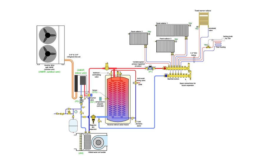
This system uses a low-ambient “split system” air-to-water heat pump with a variable speed compressor. The outdoor unit is connected to the indoor unit by two refrigerant lines and a communications cable. No water is present outside the building, and thus no antifreeze is used in the system.
Another anchor component in this system is the reverse indirect water heater. It provides thermal mass for buffering what could be an extensively zoned heating distribution system. It also enables domestic water heating. The heat pump maintains the water in this tank at an elevated temperature. The tank is supplied with several copper or stainless steel coils suspended within its pressure vessel. Domestic water passes through these coils and absorbs heat from the surrounding water.
The system’s ability to heat domestic water depends on the temperature of the water in the tank shell. If the heat pump maintains this temperature between 110° F and 120 °F, the domestic water can be heated to a delivery temperature in the range of 105° in a single pass through the internal coils. However, if the tank temperature is based on outdoor reset control, the temperature rise of domestic water heating diminishes as outdoor temperatures increase. Outdoor reset control of the tank temperature will significantly improve the seasonal space heating COP of the heat pump. However, it also requires the temperature of the preheated domestic hot water to be “topped off” by some other heat source. One option for providing this supplemental heat is an electric tankless water heater, piped as shown in Figure 2.

Space heating is provided through a simple homerun distribution system using 1/2-inch PEX tubing routed to and from each heat emitter. A low-power variable-speed pressure-regulated circulator, (P1), set for constant differential pressure mode supplies flow to a combination of panel radiators, a towel warming radiator, and a small area of radiant floor heating. All three panel radiators and the towel warming radiator are equipped with non-electric thermostatic valves that sense room air temperature and regulate flow through their associated heat emitter to maintain a set comfort level. Flow through the floor heating circuit is also regulated by a thermostatic valve. That valve is located in an accessible cavity under the floor. A capillary tube connects it to a wall-mounted setting dial. The manifold station supplying the home run circuits has two spare connections. These allow heat emitters to be easily added in the future, if, for example, an addition is made to the house.
The heat emitter selections show the versatility of this approach. There could be more or less of any specific type of emitter in a specific system. However, it is important that all the emitters are sized to operate at the same supply water temperature under design load. Doing so eliminates the need for mixing valves and additional circulators. Simple is better.
When the system operates in heating mode, the variable-speed pressure-regulated circulator (P1) remains on. Its speed automatically changes to maintain a constant differential pressure as the thermostatic valves on the heat emitter circuits regulate flow. If all heat emitter circuits are closed the circulator shifts to a “sleep” mode in which it runs at a low speed on approximately 9 watts of electrical input power. The circulator “wakes” into normal pressure-regulated operation as soon as one or more thermostatic valves begins to open.
There is no room thermostat for heating mode. The heat pump and its associated circulator are turned on when the water temperature at sensor (STS) in the tank drops to a predetermined minimum value (based on either setpoint or outdoor reset control).
The diverter valve (DV1) is powered on whenever the heat pump operates in heating. It directs flow leaving the heat pump to the header piping above the tank. If none of the heat emitters are active, all flow passes into the top of the tank. If some heat emitters are active, the flow divides at the upper tank header, some passing to the active heat emitter circuits and the rest passing into the tank. This “2-pipe” tank configuration allows the possibility of hot water passing directly from the (operating) heat pump to any active heat emitters.
Chilling out
During cooling mode, the diverter valve remains unpowered. This directs flow leaving the heat pump to the chilled water coil in the air handler. The heat pump’s compressor varies its speed to maintain a preset chilled water outlet temperature of 50°.
If the temperature of the tank drops below a preset minimum value while the system is operating in cooling mode, the heat pump temporarily switches to heating mode to restore the tank temperature. This “priority” mode is necessary to ensure adequate domestic hot water during cooling mode operation. Given the warm outdoor temperatures present during cooling operation, the time required for the heat pump to restore the tank temperature is likely to be short, perhaps only five to 10 minutes. The lack of cooling during this time is unlikely to be of any consequence.
Small matters
It’s easy to focus on the “big” hardware in this system, specifically, the heat pump and the reverse indirect water heater. They’re certainly important, but so are some small less obvious details. They include:
- All piping and components that convey chilled water are insulated and vapor sealed;
- A spring-loaded check valve prevents chilled water migration into the lower tank header;
- The domestic water coil assembly in the reverse indirect tank is equipped with isolation/flushing valves at its inlet and outlet connections. These valves allow the coil assembly to be isolated from the remainder of the domestic plumbing and flushed with a mild acid solution to remove any accumulated scale;
- The reverse indirect tank provides hydraulic separation between circulators (P1) and (P2);
- The generously sized header piping on the tank helps ensure good hydraulic separation between these circulators;
- The magnetic dirt separator helps keep the heat pump’s heat exchanger clean. It also gathers iron oxide particles that might otherwise collect in the circulators;
- Installing the diverter valve so the port leading to the indirect is closed, other than when the heat pump is running in heating mode, prevents flow returning from the space heating circuits from passing through the heat pump when it’s off, thus reducing extraneous heat loss; and
- A thermostatic mixing valve is installed to ensure that the domestic hot water temperature supplied to the fixtures doesn’t exceed 110°.
The brains
The control wiring for the system shown in Figure 1 is shown in Figure 3.
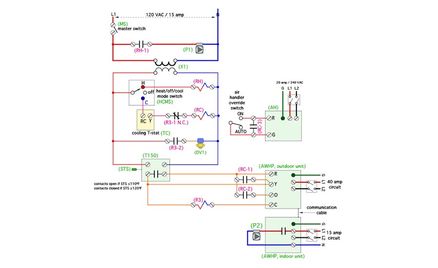
The electrical schematic is structured as a ladder diagram. It uses three 3PDT relays, all with 24VAC coils, to achieve the necessary “hard wired” control logic for space heating, cooling and domestic water heating priority during cooling mode operation. A 3PDT relay has three isolated poles (e.g., pathways for electricity), each with a normally open and normally closed contact. Having these extra poles comes in handy, as you’ll see when cooling mode operation is explained.
Over the years, I’ve used hundreds of Dayton 5X840 3PDT relays mounted in Dayton 5X853 relay sockets. I like to mount these sockets to a DIN rail that’s fastened inside a generously size electrical utility box. These are industrial quality components. I don’t recall a single one ever failing.
Several independent circuits supply power to this schematic. A 120 VAC/15 amp circuit supplies power through a master switch (MS) for heating circulator (P1) and transformer (X1). This transformer reduces this voltage to 24 VAC to supply the cooling thermostat (TC), the temperature setpoint controller (T150) and diverter valve (DV1). Separate 240 VAC circuits supply the air handler, the outdoor unit of the air-to-water heat pump and the indoor unit of this heat pump.
A master switch controls power to all control circuits. If the master switch is off, the control system cannot operate the heat pump, circulators, air handler or other electrical hardware in the system.
Modalities
A heating/cooling mode switch (HCMS) determines if the system operates in heating mode, cooling mode or remains (off).
When the heating/cooling mode switch (HCMS) is set to heating, relay coil (RH) is powered on. Relay contact (RH-1) closes to supply 120 VAC to the heating distribution circulator (P1). Once energized this circulator automatically adjusts its speed and input power to maintain a preset differential pressure. As the thermostatic valves on the heat emitter circuits open, the control logic in circulator automatically detects an “attempt” to reduce differential pressure. It responds by increasing motor speed to restore the preset differential pressure, and vice versa. Think of it as simple but effective “cruise control” for flow to the distribution system.
When the heating/cooling mode switch (HCMS) is set to heating, 24 VAC is also sent to the temperature setpoint controller (T150). This controller monitors the temperature at sensor (STS) at the mid-height of the reverse indirect tank. When this temperature drops to 110° or less, the contacts in the (T150) controller close. This allows 24 VAC from the heat pump’s internal transformer to pass from the (R) terminal to the (Y) terminal. The heat pump responds by turning on (P2).
After a flow sensor in the heat pump verifies adequate flow, the compressor turns on. Relay coil (R3) closes whenever the temperature setpoint controller (T150) calls for the heat pump to operate. Relay contact (R3-2) closes to pass 24 VAC from transformer (X1) to the diverter valve (DV1), which opens its normally closed port to allow flow from the heat pump to the tank header. The heat pump, circulator (P2) and diverter valve (DV1) continue to operate in this manner until the temperature at sensor (STS) reaches 120°, at which point, they turn off. This operation maintains the temperature of the water in the reverse indirect water heater high enough to fully heat domestic water to a delivery temperature of 105°.
When the mode switch is set to cool, 24 VAC from transformer (X1) passes to the (RC) terminal of the cooling thermostat. When this thermostat calls for cooling, 24 VAC passes to its (Y) terminal and continues through the normally closed relay contact (R3-1 N.C.) to energizes relay coil (RC). Relay contact (RC-1) closes to allow 24 VAC from the heat pump’s internal transformer to reach the heat pump’s (Y) terminal. This turns on the heat pump’s circulator (P2). When flow through the heat pump is verified by an internal flow switch, the heat pump’s compressor also operates. Relay contact (RC-2) passes 24 VAC from the heat pump’s internal transformer to its (O) terminal. This energizes the heat pump’s reversing valve for cooling mode operation. Relay contact (RC-3) closes to allow a low voltage circuit in the air handler to turn on the blower. In this mode, the heat pump continuously monitors the chilled water temperature leaving the indoor unit. The compressor speed varies as necessary to maintain this temperature close to 50°. This mode of operation continues until the cooling thermostat (T1) is satisfied.
The ability of the “inverter” drive heat pump to reduce compressor speed as necessary to maintain a constant chilled water temperature allows for the air handler coil to be slightly smaller than the rated capacity of the heat pump, without need of buffering. This is beneficial because the cooling load of most buildings in cold climates is significantly smaller than design heating load. Thus a nominal 4 to 5 ton air-to-water heat pump with a variable speed compressor can be matched to a nominal 3-ton air handler for cooling. Warning: If you’re planning to use a heat pump with a fixed speed compressor along with an air handler having a cooling capacity less than that of the heat pump, you need a buffer tank. Without it, you’re headed for short cycling and excessive wear on the heat pump.
Relay (R3) is used to temporarily interrupt cooling operation if the temperature setpoint controller (T150) determines that the tank requires heating to allow uninterrupted domestic hot water. Relay contact (R3-1 N.C.) breaks the 24 VAC signal from the cooling thermostat to relay (RC) during this mode of operation. Relay contact (R3-2) closes to supply 24 VAC from transformer (X1) to energize the diverter valve (DV1).
The air handler (AH) is also wired to a manually operated switch that allows it to be turned on at times when cooling is not needed. This provides for whole house air circulation to distribute solar heat gains, or circulate air from a heat recovery ventilator. The air handler (AH) continues to operate as long as this manual switch is in the “on” setting, regardless of which mode the system is in.
By now, I’m sure many of you recognize the potential to customize this template for your specific projects. Possible variations include:
- Adding more homerun circuits and heat emitters;
- Keeping all heat emitters the same type;
- Include an electric boiler as a backup heat source;
- Tying in an existing boiler for supplemental heat;
- Using a reverse indirect equipped with immersion heating elements for supplemental heating;
- Using a standard buffer tank with an external “side arm” brazed plate heat exchanger for domestic water heating; and
- Using an outdoor reset controller rather than a temperature setpoint controller to boost space heating COP. If you do this, be sure you have a supplemental heat source to maintain adequate domestic hot water temperature.
Heat pumps could be “magic sauce” that pushes hydronics to previously unattainable acceptance in North America. This template, or some variation on it, should help you configure your knowledge of modern hydronics technology around this new market opportunity.

