I recently reviewed a proposed biomass boiler system involving the addition of two pellet boilers and thermal storage to a system that originally had an outdoor wood furnace. The latter was being removed and replaced by the pellet boilers.
The system supplied heat to two buildings, one located about 200 ft. from the other. One building housed all the boilers and thermal storage. The other received heat through underground runs of insulated 1.5-in. diameter PEX tubing. Each building had multiple zones. One building was heated by finned-tube baseboard, the other by in-slab radiant heating. The latter had existing circuits that were partially routed through outdoor slab areas for snow melting.
The two pellet boilers had rated outputs of about 89,000 Btu/h and 51,000 Btu/h. The plan was to use the 89,000 Btu/h boiler for “base loading” and supplement it, when necessary, with the 51,000 Btu/h boiler. A propane-fired mod/con boiler rated for 180,000 Btu/h was included for full backup heating if necessary. That boiler could modulate its output down to 18,000 Btu/h as needed to provide good load tracking and minimize potential for short-cycling.
Due to door size limitations, the required thermal storage would be provided by two 119-gal. insulated thermal storage tanks.
Selective storage
Because the propane-fired boiler only is used if the pellet boilers can’t sustain adequate heat output, and given its wide modulation range, there is no need to pass the heat it produces through thermal storage. Doing so would be undesirable from a thermodynamics perspective. It would convert high-grade energy (propane) into low-grade energy (heat) before that energy was needed by the load. Once such a conversion takes place, it’s a race against time to control when and where the low-grade energy goes within the system. In simple terms: It’s easier and much more “controllable” to store energy as propane rather than as heat.
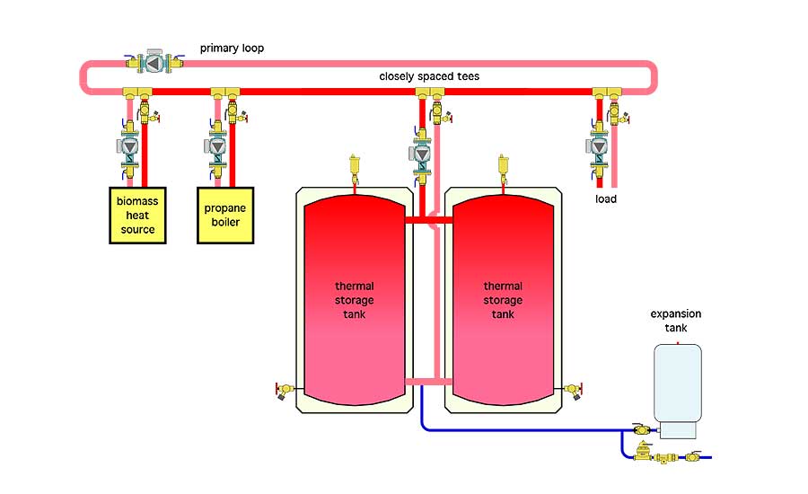
An initially proposed concept that would prevent heat produced by the propane boiler from interacting with thermal storage was to connect thermal storage as a secondary circuit to a primary loop, as shown in Figure 1.
While it would be possible to turn off the secondary circulator leading to the thermal storage tanks and thus isolate them when the propane boiler is on, the primary/secondary piping configuration creates another problem: How to get the hottest water at the top of the thermal storage back into the primary loop? Doing so would require flow reversal depending on whether the thermal storage tanks are absorbing heat from the primary loop or adding heat to that loop.
Flow reversal is possible using either a single motorized 4-way valve in combination with a single circulator or using two circulators and a 3-way diverter valve. In addition to piping details and hardware, flow reversal requires controls that know exactly when heat is, or should be, added to thermal storage or removed from it. In short, it’s possible but complicated and more expensive than other options.
A single entity
Think of the combination of one or more biomass boilers and their associated thermal storage as a single entity that we’ll call the “biomass heat source.” Heat supplied from this entity might come directly from the biomass boiler(s), or from thermal storage or from both at the same time. It depends on the firing status of the biomass boiler(s) and the status of the load(s).
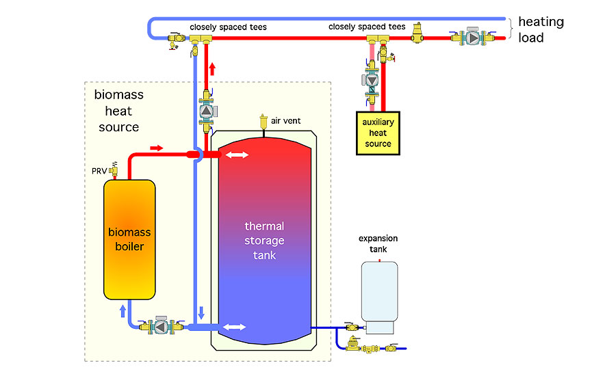
The “biomass heat source” can be treated as if it is a fixed lead heat source to the distribution system, in combination with one or more auxiliary boilers as the second stage or auxiliary heat source. This combination is shown in Figure 2.
Putting it all together
Figure 3 shows a piping schematic for a system that embodies all the heat sources and loads described at the beginning of this column.
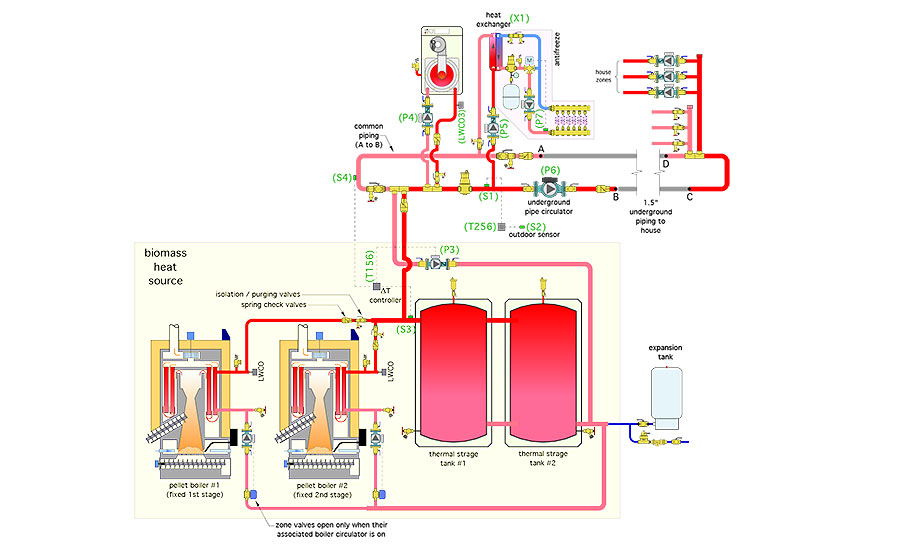
Each pellet boiler has its own circulator and a zone valve on its inlet piping that opens when the associated boiler circulator is on. The zone valves prevent any flow returning to the lower tank header from passing through a pellet boiler that’s off. This is important because allowing flow of heated water through an unfired boiler increases heat loss through the boiler jacket and up the chimney. Convective heat loss up the chimney is more of an issue with pellet boilers because they do not have automatic motorized flue dampers.
The pellet boilers in this system have internal details and control features that prevent sustained flue-gas condensation. Thus, there is no need for external mixing devices to boost the inlet water temperature above dew point. Other boilers may not have such internal details and would require external mixing assemblies to keep the inlet water temperature above a minimum of 130° F whenever possible.
The pellet boilers connect to a common header system leading to the thermal storage tanks. Those tanks are configured so hot water coming from the pellet boilers can be partially or fully passed to the distribution system before entering either tank. Flow to the distribution system occurs when circulator (P3) is operating. When (P3) is off, the biomass heat source is isolated from the distribution system. Any flow coming from the pellet boilers and not passed to the distribution system enters the thermal storage tanks.
This piping configuration reduces flow velocity entering the tank when the distribution system is operating at the same time as one or both pellet boilers. Lower entering flow velocity helps preserve (desirable) temperature stratification within the tanks.
The tanks are “close coupled” using short and generously sized piping between the tanks. A semi-flexible coupler, with suitable pressure and temperature ratings, works well here. The objective is to minimize the pressure drop through the coupling piping and thus have the two tanks act (hydraulically) as if they were a single tank.
The distribution system has two loads operating in parallel. One is a zoned space-heating subsystem supplied through insulated underground piping. Flow to this subsystem is provided by circulator (P6). The three zone circulators in the subsystem are hydraulically separated from the flow dynamics of circulator (P6) by a set of closely spaced tees. Circulator (P6) is sized based on the flow and head-loss requirements of the underground piping plus the common piping between points (A) and (B), and between points (C) and (D).
The radiant panel circuits operate with an antifreeze solution heated by the heat exchanger (X1). Primary flow to this heat exchanger is provided by circulator (P5).
Purging valves are provided on the outlet pipe of each load subsystem. Check valves or internal spring-loaded flow checks within circulators are provided to stop heat migration or flow reversal though inactive portions of the system.
The auxiliary boiler is a propane-fired mod/con. It’s connected to the distribution system using a pair of closely spaced tees for hydraulic separation. These tees are located “downstream” of the tees that connect the biomass heat source to the system. Doing so allows the thermal storage tanks to make a positive energy contribution to the distribution system at lower temperatures than would be possible if the mod/con boiler tees were upstream of the tees from the biomass heat source.
A differential temperature controller, labeled as (T156) in Figure 3, allows circulator (P3) to start only if the temperature at the upper header of the thermal storage tank, at sensor (S3), is at least 5° above the temperature at sensor (S4) on the return side of the distribution system. This prevents heat generated by the mod/con boiler from being inadvertently sent into thermal storage. It also prevents flow from what might be “cool” thermal storage into the distribution system.
An outdoor reset controller, labeled as (T256) in Figure 3, turns on the auxiliary boiler and its circulator when and if the water temperature supplied to the distribution system at sensor (S1) falls slightly below the “target” temperature that can maintain adequate heat delivery to the loads.
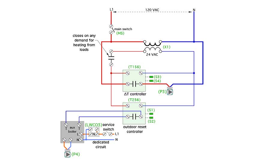
Figure 4 shows a simple electrical schematic that combines the differential temperature controller (T156) and outdoor reset controller (T256) to synergistically manage heat input to the distribution system.
We’ll get into possible control schemes for the “tandem” pellet boilers in next month’s Renewable Heating Design column.

