
Formula 1 below should be recognized by anyone who designs hydronic heating and cooling systems.
Formula 1:

Where:
Q = rate of heat transfer (in Btu/h)
f = flow rate (in gallons per minute (gpm))
∆T = temperature change (°F)
500 = a constant based on the properties of water as the system fluid
This formula can be used to calculate the rate of heat transfer when a measured flow rate of water combined with measured temperature change both exist.
For example: Consider a situation in which a heating technician reads a flow meter, or perhaps the digital display on a modern high efficiency circulator, and observes a flow rate of 3.5 gpm. The technician also uses accurate in-struments to simultaneously measure the supply water temperature and return water temperature to a hydronic dis-tribution system. The supply temperature is measured as 119° F, and the return temperature is measured as 103.5°. The flow rate and two temperatures are also observed to be stable for perhaps 30 seconds, indicating a con-dition that’s at or close to steady state. The technician also knows that the system is operating with water, rather than a solution of water and antifreeze. These measured valves can be used in Formula 1 to calculate the rate of heat transfer to the distribution system:
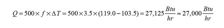
The number (27,000 Btu/h) following the “squiggly” equal sign is the rounded off value of the calculated result (27,125 Btu/h). The rounded off value reflects the fact that the flow rate and temperature readings are of limited ac-curacy, and thus it’s not possible to know that the calculated rate of heat transfer is accurate right down to the last Btu/h. In this case, the flow rate measurement of 3.5, which is only two significant digits, limits the calculated result to two significant digits, and thus 27,000 Btu/h.
If, then
It’s important to understand that Formula 1 doesn’t guarantee that a specific temperature change will occur when some desired rate of heat transfer is based on a selected flow rate.
For example, assume that the heating delivery requirement for a hydronic distribution system is 25,000 Btu/h, and that the designer selects a flow rate of 2.5 gpm. The designer then (naively) uses Formula 1 to “reveal” the temperature drop that they think will occur.
The numbers inserted into a rearranged version of Formula 1 yield the following:
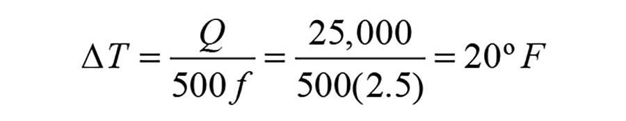
Although a 20° temperature drop is a possibility, under specific conditions, this calculated value should not be considered a guaranteed physical result. Instead, the calculated temperature drop should be interpreted as follows: If the hydronic distribution system can release 25,000 Btu/h when supplied with water at 2.5 gpm, then the resulting temperature drop will be 20°.
To see why the words “if” and “then” are important, consider the following: Suppose that the tempera-ture of the water supplied to the hydronic distribution system at a flow rate of 2.5 gpm was equal to the room air temperature. Under that condition there would be no temperature difference between the water in the system and the room air, hence there will be no heat transfer. This physical possibility is not “revealed” by the mathematics in Formula 1.
Neither is a situation where water is supplied to a hydronic distribution system at perhaps 140°, but the heat emitters in that system were sized to release 25,000 Btu/h when supplied with 180° water. Under such condition, the rate of heat release would definitely be less than 25,000 Btu/h, and the temperature drop would be less than 20°. This situation is possible, but not predictable using the mathematics of Formula 1.
If water was supplied to the same distribution system at 200°, and 2.5 gpm, the heat output of the distribution system would be greater than 25,000 Btu/h. Another real possibility that’s not discernible using Formula 1.
Math versus physics
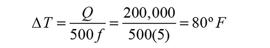
Just because the mathematics associated with Formula 1 work doesn’t mean that a given set of physical condi-tions will occur or can occur. Consider a situation where a designer needs to establish a rate of heat delivery of 200,000 Btu/h to a space that is to be maintained at 70°. The designer thinks this can be done by supplying water to the system at 140° and a flow rate of 5 gpm. Putting these numbers into Formula 1 yields:
> Figure 1.
To achieve the calculated temperature drop of 80°, the water would have to cool from an initial temperature of 140° down to 60°. This would be impossible in a room maintained at 70°. Again, this reveals the fallacy of relying on a mathematically calculated value using Formula 1 to trust that some desired physical result will or can occur.
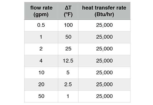
Although the expression “infinite possibilities” is frequently used as a cliche, it’s true when it comes to the number of combined flow rate and ∆T values that would satisfy the requirements for any given rate of heat transfer. Figure 2 lists just a few of these combinations that would imply a heat transfer rate of 25,000 Btu/h using water as the heat transfer fluid.
Formula 1 is a great tool when you can measure any two of the three variables (e.g., Q, f, or ∆T) and use these measured values to calculate the remaining unknown. Just don’t forget that something that’s mathematically possible isn’t automatically physically possible.


