
What characteristic do solar thermal collectors, hydronic heat pumps and thermal storage tanks supplied by biomass boilers have in common? Answer: They all perform best when coupled to distribution systems that operate at low supply water temperatures.
But that’s not what’s waiting for them in most North American homes. Instead, it’s common to encounter space heating distribution systems designed in the days of lower-cost fuels, and when boilers burning those fuels were by far the most common heat source. Heat emitters were sized around water temperatures of 180° F or higher. The design rationale was simple, higher water temperatures meant small heat emitters and lower installation cost. Boilers of that era were not designed to condense flue gases, so efficiencies in the range of perhaps 85-87% represent the practical “ceiling” of thermal performance. In short, there was little if any incentive to design distribution systems around lower water temperatures.
Fast forward to today, and a situation where an installer is asked to replace an aging boiler with an air-to-water or geothermal water-to-water heat pump. If the installer does a “cut and paste” replacement by removing the boiler and dropping a new heat pump in its place, trouble is sure to follow.
For example, most current generation water-to-water and air-to-water heat pumps can only produce water temperatures in the range of 120° to 130° F. If saddled to a distribution system that was sized to release design load output at 180° F average water temperature, the heat pump will quickly trip off on a high-temperature limit, requiring a manual reset after each trip. The existing distribution system simply cannot release heat at the same rate as the heat pump is adding heat when operating at a water temperature 50° to 60° F lower than what it was designed for.
Moving downward
There are two fundamental ways to reduce the supply water temperature of any hydronic heating system. The first is to reduce the design load of the building envelope through improvements such as added insulation, better windows and lower air leakage, and second, add heat emitters to the existing system. A combination of these two approaches is also possible.
Building envelope improvements reduce the design heating load of the building. After these improvements are made, the existing hydronic distribution system can — without modification — meet the reduced design load while operating at lower supply water temperatures.
In theory, and discounting any offsets due to internal heat gain, the change in supply water temperature is proportional to the change in design heating load. The new supply water temperature can be determined based on the same concepts used for outdoor reset control. It can be calculated using Formula 1:
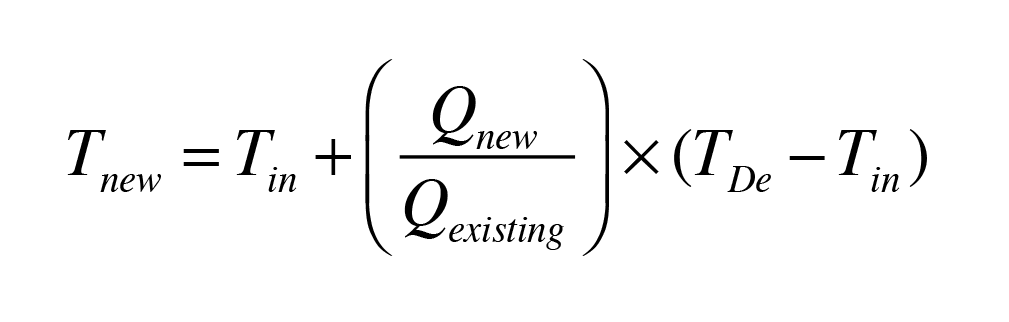
Where:
Tnew = supply water temperature at design load after building envelope improvements (°F)
Tin = desired indoor air temperature (°F)
Qnew = design heating load after building envelope improvements (Btu/h)
Qexisting = existing design heating load (before improvements) (Btu/h)
TDe = existing supply water temperature at design load (before improvements) (Btu/h)
For example, consider a building that has a design heating load of 100,000 Btu/h, based on maintaining an interior temperature of 70° F. The existing hydronic distribution system uses standard finned-tube baseboard and requires a supply water temperature of 180° F at design load conditions. Assume that improvements to the building envelope have reduced the design load from 100,000 Btu/h to 70,000 Btu/h. The new supply water temperature to the existing distribution system under design load conditions is calculated using Formula 1:
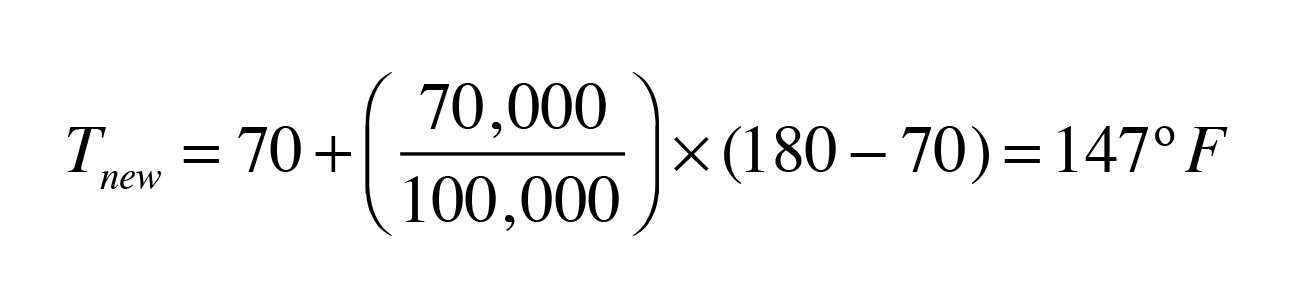
Figure 1 shows the supply water temperature versus outdoor temperature for the original load, as well as the reduced load after the building envelope improvement were made. This figure assumes that the outdoor design temperature is 0° F.
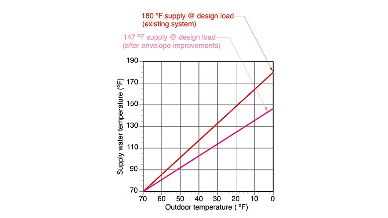
In this case, reducing the design heating load from 100,000 Btu/h to 70,000 Btu/h reduced the required supply water temperature at design load from 180° F to 147° F. Although this is certainly an improvement, it is still substantially above what some renewable energy heat sources can consistently provide.
More emitters
If reducing the design heating load of the building does not lower the required water temperature to the desired value, it will be necessary to add heat emitters to the system.
If the original system used finned-tube baseboard heat emitters, it may be possible to add more of the same emitters. Another option might be to change some existing baseboard for “high-output” baseboard. It’s also possible to add different types of heat emitters such as panel radiators, fan-coils or select areas of radiant panels.
The choice of which type of heat emitter to add will depend on several factors, including:
- Availability of different makes/models of heat emitters;
- Cost of the new heat emitters;
- How difficult it is to integrate the new heat emitters into the building;
- Aesthetic preferences;
- Floor coverings (in the case of radiant floor panels);
- Surface temperature limitations (in the case of radiant panels); and
- The specific supply water temperature that is to supply design load output in the renovated distribution system.
More baseboard
Let’s proceed with the assumption that more fin-tube baseboard will be added. The following procedure can be used to calculate the amount of baseboard to be added to reduce the supply water temperature at design load to a pre-determined value. It assumes that the added baseboard is the same make and model as the existing baseboard. It also assumes that the existing baseboard is a standard residential-grade product with nominal 2.25-inch square aluminum fins with an I=B=R rated output of approximately 600 Btu/h/ft at 200° F water temperature.
Step 1: Accurately determine the building’s design heat load using Manual J or equivalent procedures.
Step 2: Determine the total length of finned-tube in the existing distribution system. Do not include the length of tubing that doesn’t have fins. The existing finned-tube length will be designated as Le.
Step 3: Determine the desired (lower) supply water temperature for which the system is to supply design load output. A suggested value is 120° F.
Step 4: Estimate the lower average circuit water temperature by subtracting 5° to 10° F from the supply water temperature determined in Step 3.
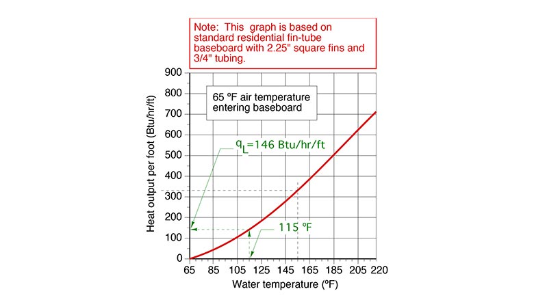
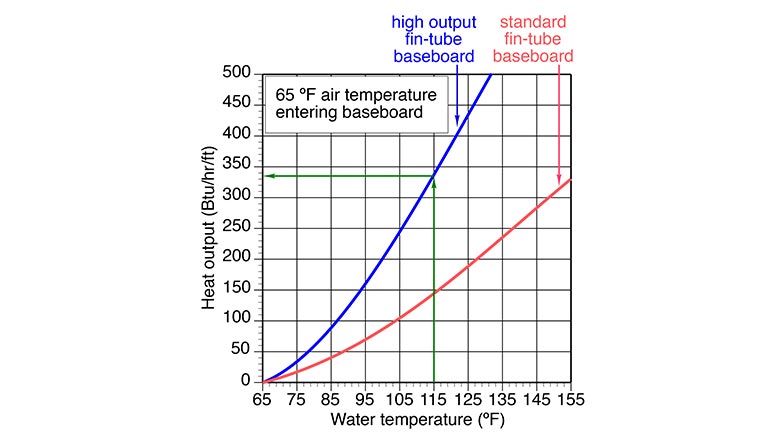
Step 5: Find the new average circuit water temperature on the horizontal axis of the graph in Figure 2. Draw a vertical line up from this point until it intersects the red curve. Draw a horizontal line from this intersection to the vertical axis of the graph, and read the heat output of the finned tube at the lower average circuit water temperature. This number is designated as qL. The green lines and numbers in Figure 2 show how qL is determined for an average circuit water temperature of 115° F.
Step 6: Determine the length of baseboard to be added using Formula 2.
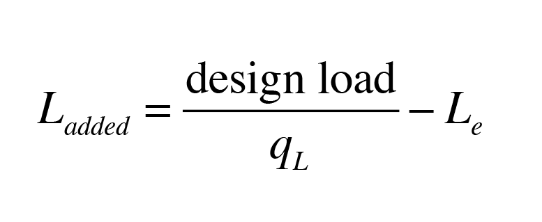
Where:
Ladded = length of finned-tube of same make/model baseboard to be added (feet) design load = design heating load of building (Btu/h)
qL = output of baseboard at the lower average circuit water temperature (Btu/h/ft)
Le = total existing length of baseboard in system (feet)
Here’s an example. Assume a building has a calculated design load of 40,000 Btu/h, and its distribution system contains 120 feet of standard residential finned-tube baseboard. It is currently heated by a conventional cast iron boiler. The goal is to reduce the supply water temperature to 120° F at design conditions, using more of the same baseboard. Assume the temperature drop of the distribution system is 10°F. Estimate the amount of baseboard that must be added:
Solution:
Step 1: The design load has been calculated as 40,000 Btu/h.
Step 2: The total amount of finned-tube in the system is 120 feet.
Step 3: The lower supply water temperature at design load will be 120° F.
Step 4: The lower average circuit water temperature will be 120 - (10/2) = 115° F.
Step 5: The output of the finned-tube at an average circuit water temperature of 115° F is determined from Figure 2 as 146 Btu/h/ft.
Step 6: The required additional length of baseboard is now calculated using Formula 2:
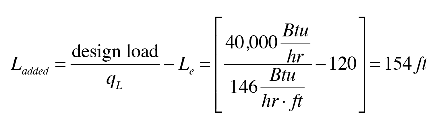
Although it might be possible to add 154 feet of baseboard to the system, it would require lots of wall space. In most buildings, adding this much baseboard is not a practical solution. Alternatives include using baseboard with higher heat output or using other types of heat emitters to achieve the necessary design load output.
Bigger fins/shorter lengths
Another option is to consider adding “high output” finned-tube baseboard rather than standard baseboard. Figure 3 shows the heat available from one brand of high-output baseboard (shown as the blue curve), and for comparison, standard residential baseboard (shown as the red curve).
The steps of the previous procedure can be modified to determine the amount of high-output finned-tube baseboard that is required to reduce the supply water temperature to the system under design load.
Steps 1-4: Same as before.
Step 5: Determine the output of high-output baseboard at the average circuit water temperature using Figure 3 (or manufacturer’s literature for a specific make and model).
Step 6: The required length of high output baseboard to add to the system is found using Formula 3.
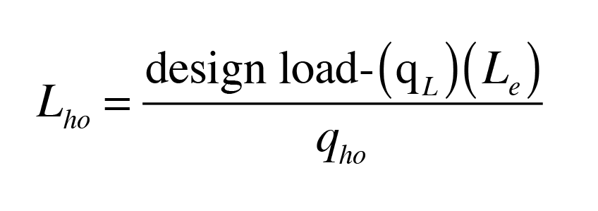
Where:
Lho = length of high output finned-tube baseboard to be added (feet) design load = design heating load of building (Btu/h)
qL = output of existing baseboard at the lower average water temperature (Btu/h/ft)
Le = total existing length of baseboard in system (feet)
qho = output of high output baseboard at the lower average water temperature (Btu/h/ft)
Here’s another example: Assume a building has a calculated design load of 40,000 Btu/h, and its distribution system contains 120 feet of standard residential finned-tube baseboard. The goal is to reduce the supply water temperature under design load to 120° F. Additional high-output baseboard will be added to allow this lower water temperature operation. Assume the temperature drop of the distribution system at design load is 10° F, and this existing baseboard has the same output as in the previous example (146 Btu/h/ft at average circuit water temperature of 115° F). Determine the amount of high-output baseboard required based on the performance shown in Figure 3.
Solution:
Step 1: The design load has been calculated as 40,000 Btu/h
Step 2: The total amount of finned-tube in the system is 120 feet
Step 3: The new lower supply water temperature at design load will be 120° F
Step 4: The new lower average circuit water temperature will be 120 - 5 = 115° F
Step 5: The output of high output finned-tube at an average water temperature of 115° F is determined from Figure 3 as 335 Btu/h/ft.
Step 6: The required length of high output baseboard to add to the system is found using Formula 3.
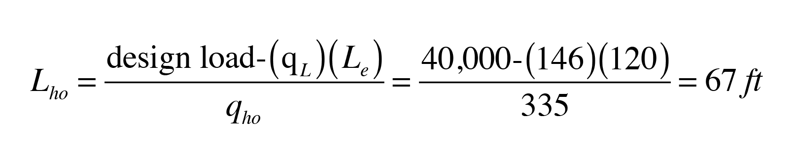
Although this is a substantial reduction compared to the 154 feet of additional standard baseboard required in the previous example, it is still a substantial length. The building must be carefully evaluated to see if this additional length of baseboard can be accommodated.
If the added length of high output baseboard cannot be accommodated, another option is to raise the supply water temperature constraint from 120° to 130° F under design load conditions. This would reduce the amount of added high-output baseboard to 40 feet. However, the higher the water temperature the lower the efficiency of the renewable heat source.
Adding other heat emitters
If the amount of finned-tube baseboard that needs to be added is beyond what can be accommodated, there are several other added heat emitter options. They include panel radiators, fan-coils or areas of radiant floor, radiant wall or radiant ceiling panels. In each case, the selection of these new heat emitters should be based on a selected supply water temperature at design load, along with a “credit” for the existing heat emitters in the system operating at the lower supply water temperature. The fundamental concept is represented by Formula 4.
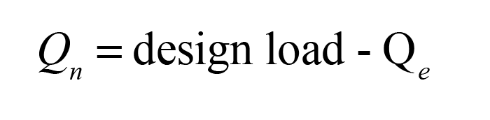
Where:
Qn = required heat output of the new heat emitters at lower supply water temperature (Btu/h) design load = the design heating load of the building (Btu/h)
Qe = heat output of existing heat emitters at the lower supply water temperature (Btu/h)
Once the value of Qn is determined, the designer can use tables or graphs from manufacturers to determine the heat output of specific heat emitters based on the average water temperature within them. Remember that the average water temperature will be 5° to 10° F lower than the supply water temperature.
The goal is to select a grouping of new heat emitters with a total heat output that’s approximately equal to the value of Qn in Formula 4.
Here’s a final example. Assume a building has a calculated design load of 40,000 Btu/h, and its distribution system contains 120 feet of standard residential finned-tube baseboard. The goal is to reduce the supply water temperature to 120° F under design load conditions. Panel radiators are available in 24” x 72” sizes that can release 4,233 Btu/h when operated at an average water temperature of 115° F in rooms with 70° F interior temperature. How many of these radiators are necessary to meet the design load?

Solution: First, use Formula 4 to determine the output required of the new radiators. The number of radiators needed is then found as follows:
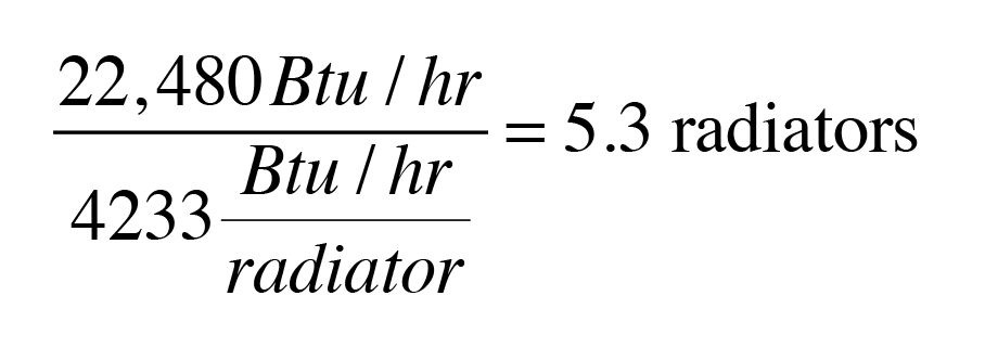
The designer could either add six of these panel radiators or choose a slightly higher supply water temperature and use 5 radiators.
Another option is to use panel radiators of different sizes, provided that their total output at the lower supply water temperature could meet the value of Qn. In this example, the six new radiators would be combined with the 120 feet of existing baseboard to provide the 40,000 Btu/h design load.
A similar calculation could be made for fan coils, air handlers or other heat emitters.
In the case of radiant panels, the designer needs to determine the output of each square foot of panel based on the lower average circuit temperature, and the specific construction of the panel. The total required panel area is found by dividing this number by the value of Qn.
Piping options
Once the amount of additional baseboard is determined, designers can turn their attention to how it should be piped into the distribution system. We’ll cover that in part two.


