
Most thermally-based renewable energy heating systems have controllers measuring and responding to temperature. Common examples are set-point controllers, outdoor reset controllers, mixing controllers and differential-temperature controllers.
In residential and light-commercial systems temperatures are sensed by NTC (negative temperature coefficient) thermistor sensors. These solid-state devices decrease their electrical resistance as their temperature increases and vice versa. Figure 1 shows a temperature vs. resistance chart for a common “10K” NTC thermistor sensor that’s commonly used in the industry. The “10K” designation indicates the sensors resistance of 10,000 ohms at 77° F (25° C).

The relationship between the sensor’s temperature and its electrical resistance is not linear, but it is repeatable. Modern digital controllers easily can translate the electrical resistance of the sensor circuit into an inferred temperature value based on firmware that maps the temperature vs. resistance curve.
The type of thermistor sensor used in most HVAC applications consists of a solid-state thermistor bead, an enclosure and lead wires. Thermistor beads can be very small and have very fine attached wires. Figure 2 shows just how small some thermistor beads are.
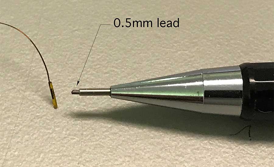
Tiny thermistor beads with fine wires don’t lend themselves to the handling and placements required in HVAC applications. The solution is to encapsulate the bead in an enclosure that can withstand more physical force and connect it to lead wires rugged enough for installers. During manufacturing, the lead wires are soldered to the thermistor bead (or a tiny circuit board holding the bead). This assembly is then inserted into the enclosure “can,” and a potting material is poured in to permanently seal it in place and protect it against moisture.
Sensor enclosures are made of a highly conductive metal such as copper, brass or stainless steel. The high conductivity minimizes the difference between the temperature of the sensor’s outer surface and the temperature at the thermistor bead. For most heating or cooling system control applications this temperature difference is tiny and of no concern.
The leads attached to thermistor sensors may not be long enough to reach from the installed sensor to the controller. A cable must be used to complete the circuit between the sensor and controller. The sensor and cable together forms the sensor circuit and the resistance of the sensor circuit is what the controller “feels.” Anything that adds significant resistance to this circuit makes the controller think the temperature at the controller is lower than it actually is.
Designers should verify the minimum wire size (e.g., the largest AWG number) that the controller manufacturer allows for connecting the sensor to the controller. They should also verify the maximum sensor cable length.
I suggest nothing smaller than 18 AWG copper wire for 10K thermistor sensors. That wiring has a resistance of 0.0064 ohms per-ft. If the sensor was located 250 ft. from the controller it would require about 500 ft. of sensor wire (e.g., 250 ft. from the controller to the sensor location and 250 ft. back to the controller). The total resistance of the wire would be about 3.2 ohms. This would add to the resistance of the sensor itself. For a 10K thermistor at 77°, the cable only would represent 0.03% of the circuit resistance, which would only make a tiny and insignificant difference between the actual sensor temperature and the temperature the controller “feels” at the terminals where the sensor cable connects to the controller.
The bond between the sensor lead wires and the sensor cable can add significant resistance to the circuit. One situation where this can become a problem is where sensor lead wires connect to cable wires using standard wire nuts and that connection is subsequently exposed to moisture. An example would be a sensor lead to a cable connection that’s outside or in a high-moisture environment.
Moisture that collects within the wire nut can cause corrosion at the junction between the sensor leads and cable wires. Over time this increases the resistance of the sensor circuit and “fools” the controller into thinking the sensor temperature is lower than it actually is. This was a common problem with early-generation solar-thermal systems where the wire nuts connecting the sensor lead to the cable were exposed to weather.
If you need to join the leads from exterior-located thermistor sensors to a cable, make every effort to locate the joint inside and where it’s accessible. If the joint has to be outside, or otherwise exposed to a high moisture environment, use a gel-fired compression connector, such as used for telephone wiring, for the splice. The gel inside these connectors provides a waterproof seal of the electrical bond.
Sensor circuits also can be affected by strong electromagnetic fields, which can induce currents in sensor cables that inevitably interfere with controller operation. To reduce the chances of such interference, avoid running sensor cables next to or in the same conduit as AC wiring.
If the sensors must be installed near large motors, light ballasts or large transformers, use cabling with twisted-pair wires, or even better, shielded cable. The latter has a metal foil layer between the exterior insulation and internal conductors. One end of this metal foil should be fastened to an electrical ground. The other end of the foil should be electrically isolated.
Mount up
Controllers only can respond to the information they receive from their sensor(s). If temperature sensors are improperly mounted, the temperature the controller “feels” can be different from the temperature the sensor was intended to detect.
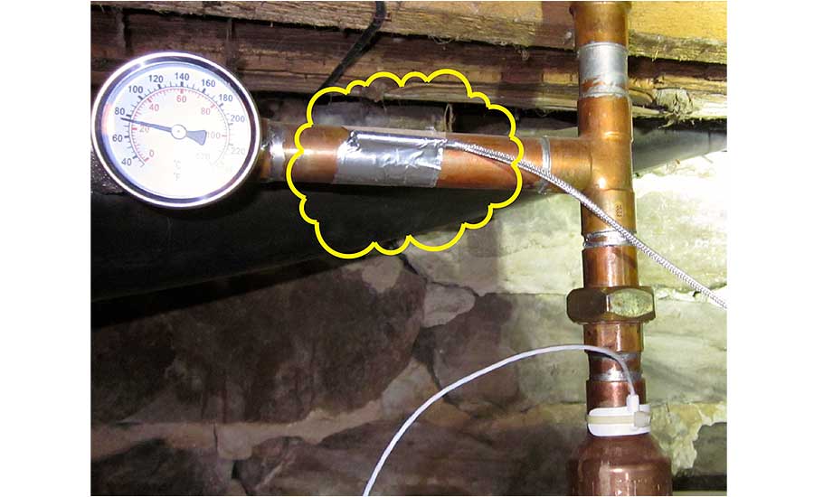
Figure 3 shows an example. The temperature sensor highlighted in yellow is taped to copper tubing. Its intended purpose is to detect the water temperature in the upper portion of a thermal storage tank, the top of which can be seen in the lower portion of the photo. A pellet boiler will be turned on base on the temperature this sensor reports. Instead of its intended measurement, this sensor will report a temperature between that of the tube surface and the surrounding air. It could be many degrees different from the temperature in the upper portion of the thermal storage tank. Needless to say the pellet boiler was not operating as expected.
When the temperature of fluids within tanks is to be measured, the sensor should be mounted in a well that’s threaded into an appropriate tank tapping. Prior to inserting the sensor, a small amount of thermal paste (e.g., a mixture of aluminum powder and grease) should be injected into the end of the well using a plastic syringe. The sensor body should also be coated with thermal paste before it’s inserted in the well.
The objective is to completely fill the gap between the sensor body and inside surface of the well with thermal paste as shown in Figure 4. Doing so improves conductivity, reduces the time lag between changes in water temperature and when those changes are detected by the sensor.
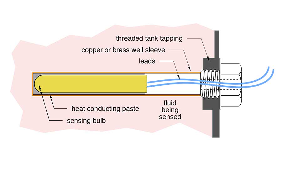
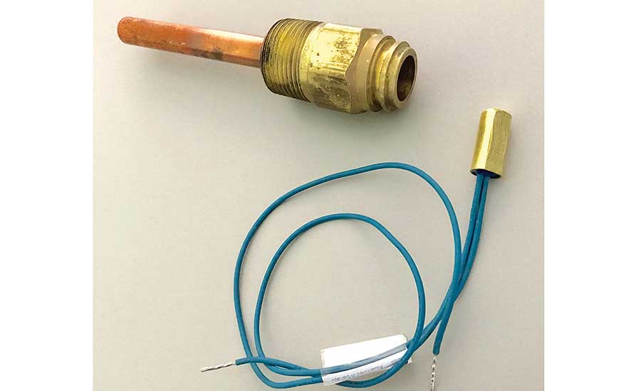
Figure 5 shows a Honeywell copper sensor well and a 3/8” diameter thermistor sensor that fits nicely inside this well, leaving just enough space for thermal paste. These wells are available in either 1/2” or 3/4” MPT threads. Many thermal storage tanks have 1/2” or 3/4” FPT threaded tapings to receive these wells. When this type of well needs to go into tanks with 1.5” or 2” FPT tapings, use a brass bushing for the size transition.
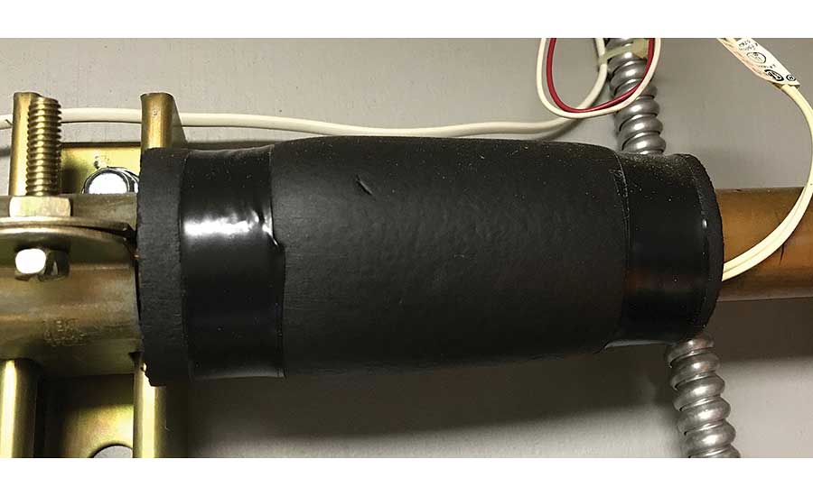
It’s also possible to mount sensors to the surface of copper tubing. Some sensors have a small concave channel on their housing, allowing the housing to “saddle” the pipe and thus have more contact surface area. Sensors mounted to copper tubing should be secured with two nylon pull-ties rated to handle the temperature the pipe may experience. Standard pull-ties will harden over time and eventually break. A small dab of thermal paste should be placed between the sensor and pipe surface. After the sensor is secured with the pull-ties, a nominal 6” length of insulation should be placed and centered over the sensor. The insulation sleeve should be sealed from air penetration at both ends. I prefer to use a high-grade electrical tape for this sealing, as shown in Figure 6.
It’s also possible to make a sensor well using copper tubing closed at the end with a soldered cap. The length of the well is whatever you need. This is especially helpful when you need to place a sensor at a specific height within a tank, as shown in Figure 7.
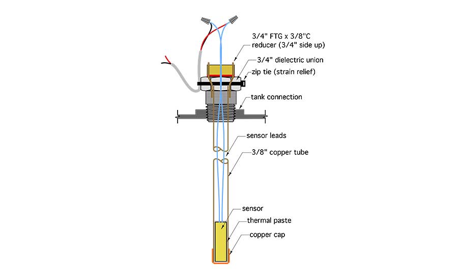
A 3/8” type M copper tube has an inside diameter of 0.450”. A 3/8” diameter sensor housing fits into this tubing, leaving about 1/32” gap between the sensor housing and inside of the tube, which should be filled with thermal paste. The 3/8” copper tube can be soldered to a 3/4” FTG x 3/8” C reducer coupling, which then can be soldered to the 3/4” brass end of the dielectric union.
If you’re planning a long sensor well inserted through a connection at the top of the tank, be sure there’s adequate head room to insert it after the tank is in place. If there isn’t room you’ll need to insert the well before the tank is rotated into its vertical position.
It’s also important to provide strain relief for the wires connecting the sensor leads to the cable. A temperature-rated zip tie holding the sensor cable to the exterior portion of the well or another nearby solid surface generally is acceptable.
Finally, be sure you label and tag every sensor in the system. Label the sensors on the piping and electrical schematics as you design the system and attach tags to the sensors as they are installed.
Sensors are the “eyes” of temperature controllers. Those controllers only can react to what they “see.” Careful sensor placement and mounting is critical to give those controllers 20/20 vision.
This article was originally titled “Eyes of the system” in the May 2018 print edition of PM Engineer.


