


In most areas of the U.S. and Canada, solar-thermal systems require a means of freeze protection.
Options include closed-loop collector subsystems operating with glycol-based antifreezes, and so-called “drainback” systems that allow the water in the collectors and exposed piping to drain back into a portion of the system within heated space. Drainback systems can be designed around unpressurized “open” thermal-storage tanks, as well as closed tanks that operate at slight positive pressure.
Over the years I’ve come to favor pressurized drainback systems. When properly installed, with drainable collectors and properly sloped piping, these systems don’t require one drop of antifreeze. This does away with issues such as thermal breakdown of glycol solutions and need for heat-dump subsystems. Drainback systems also eliminate the need for a heat exchanger between the collector array and the remainder of a space-heating distribution system. This allows the collector array to operate at lower temperatures and higher thermal efficiencies. Pressurized drainback systems are closed to the atmosphere and not subject to corrosion issues associated with oxygen absorption from the atmosphere. Because they have captive air volumes, these systems also eliminate the need for a separate expansion tank.
As a side note, I’ve had a closed drainback solar-thermal system providing space heating and domestic water preheating for my home for the last 37 years. The original collectors were replaced at 30 years. The current collector array is shown in Figure 1.
Closing the lid
In pme’s November Renewable Heating Design column, we discussed how to size the air space at the top of an unpressurized thermal storage tank used in a solar-thermal system. This month we will switch the discussion to a closed pressurized thermal-storage tank. The piping concept is shown in Figure 2.
The air space at the top of the tank must accommodate the water that drains back from the collector array and associated piping. It also must accommodate the increased volume of heated water within the system without raising system pressure to the point where the pressure-relief valve opens.
This column describes how to determine the minimum air space volume for a vertically oriented cylindrical tank. For simplicity, the top of that tank is assumed to be flat.
To determine the required space at the top of the tank, one must establish a criteria for the changes in temperature, pressure and volume of the captive air that will occur between two limiting conditions.
One of those limiting conditions is when the system is filled with cold water and the collector circulator is off. Under this condition, all water in the system (e.g., that which will eventually be in the collectors as well as that in the tank and the distribution system) is at some initial cool temperature such as 60º F. The air at the top of the tank also is assumed to be at the same temperature. The pressure of the air at the top of the tank and in the empty collector array and piping is assumed to be as some initial pressure. It could be atmospheric pressure or a slightly higher pressure. Slight positive pressure is preferred because it helps prevent vapor flashing in the return piping when the water is at higher temperature.
The other limiting condition is when all the water and air in the system is at some maximum allowable temperature (180º for example). Under this condition the air at the top of the tank cannot exceed some limiting pressure. The limiting pressure assumed in the formulas to follow is the rated opening pressure of the pressure-relief valve at the top of the tank.
The minimum height (h) of the cylindrical air space at the top of a tank with flat ends can be calculated using formulas 1a, 1b and 1c.
Formula 1a:
Formula 1b:
Formula 1c:
Where:
h = MINIMUM height of cylindrically-shaped air space required at top of tank (inches)
d = tank diameter (inches)
vT = volume of entire tank (water and air space at top ) (gallons)
vd = volume of water in distribution system (gallons)
vc = volume of collector array + collector piping above static water level (gallons)
Dc = density of “cold” water when system is filled and pressurized (lb/ft3)
Dh = density of water in system at maximum temperature (lb/ft3)
pi = initial air pressure in tank when water is cool (psi gauge)
pRV = opening pressure of pressure relief valve (psi gauge)
Tmax = maximum temperature of water and air in system (º F)
Ti =initial temperature of water and air in system (º F)
The relationships embodied in these three formulas are based on the ideal gas law, which can be stated as Formula 2.
Formula 2:
Formula 2 states the absolute pressure of a quantity of air multiplied by its volume and divided by its absolute temperature remains a constant.
Here is an example of how these formulas can be used. Assume a tank has been selected for a drainback system. It has flat ends, a volume of 250 gal., and an internal diameter of 30 in. The volume of the collector array and piping that will be drained is 10 gal. The system is filled with water at 60º and the air space at the top is left at atmospheric pressure (e.g. gauge pressure = 0). The distribution system (exclusive of the storage tank and collector subsystem) contains 50 gal. of water. The maximum temperature condition assumes all water and captive air in the system reaches 180º. A 30 psi-rated pressure-relief valve is installed at the top of the tank. What is the minimum vertical dimension of the air space at the top of the tank to accommodate expansion?
Solution: There is sufficient information given to immediately evaluate Formula 1b:
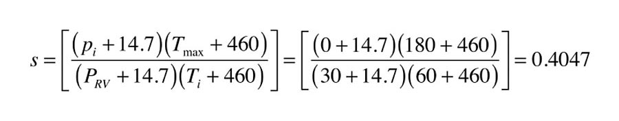
Before using formulas 1a, the values of S and R need to be determined.
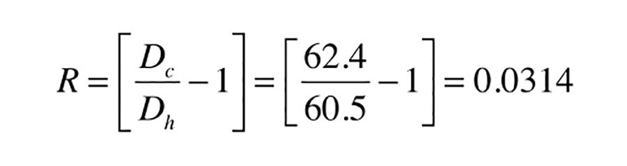
The value of R is determined by the density of water at 60º and 180º. These values can be read from Figure 3:
At 60º the density of water is: Dc = 62.4 lb/ft3
At 180º the density of water is: Dh = 60.5 lb/ft3
Formula 1c now can be used to find R:
The values of R and S, along with the other given data now can be used in Formula 1a:
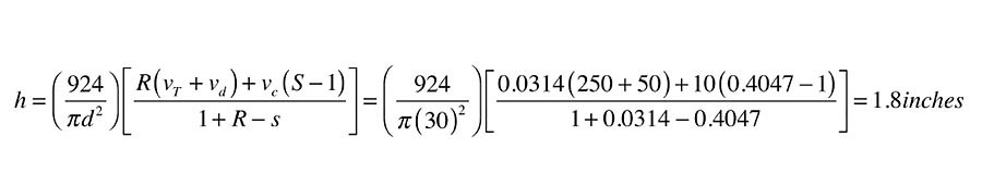
Interpretation
The calculated value of (h) means just less than 2 in. of vertical space is needed at the top of the storage tank. That air volume, in combination with the air volume in the collectors and collector piping (above the static water level), is sufficient to keep the pressure from exceeding the pressure-relief valve rating when all water and air in the system is at a temperature of 180º.
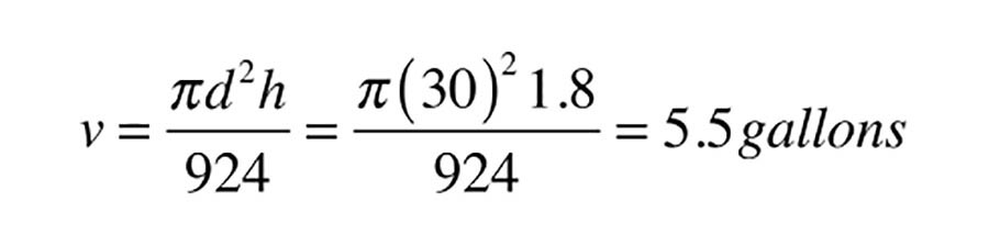
The actual volume of the expansion space within the tank can be determined using Formula 3:
Formula 3:
Where:
v = volume of the expansion space within the tank (gallons)
d = tank diameter (inches)
h = minimum height of cylindrical air space (inches)
Those familiar with sizing non-diaphragm-type expansion tanks likely will see this volume as relatively small for a system containing almost 300 gal. of water that will be heated from 60º to 180º. However, keep in mind the volume of the collectors and the piping to and from the collector also is filled will air and thus acts as an expansion space. When the collector circulator is running, this air volume is moved from the collector array into the storage tank. In this example, the collector array and associated piping adds another 10 gal. to the system’s air volume, making the total expansion air volume in the system about 15.5 gal.
More is OK
Designers should keep in mind the dimension (h), in Formula 1a, is the minimum air-space height required. The design can be made more conservative by including more air-space volume or by change the limiting constraints.
For example, the rated opening pressure of the relief valve can be reduced by 5 psi to ensure the valve will not start to operate as it approaches (but doesn’t reach) its rated operating pressure.
Another conservative assumption built into this procedure is the tank has a flat top and bottom. This is the exception rather than the rule for pressure-rated tanks. The more typical semi-elliptical heads used on most ASME-rated tanks provide additional air space within the system, as shown in Figure 4.
Anything that increases the air volume relative to water volume will reduce the pressure fluctuation as the system heats up and cools down.
It’s also important to consider the placement of the tank inlet connection from the collector array. It enters horizontally and at least a couple inches below the cold water level in the tank when the circulator is on. This helps reduce splashing noise as water enters the tank. The air return tube at the top of the tank ensures air will enter the piping returning from the collector array when the collector circulator turns off.
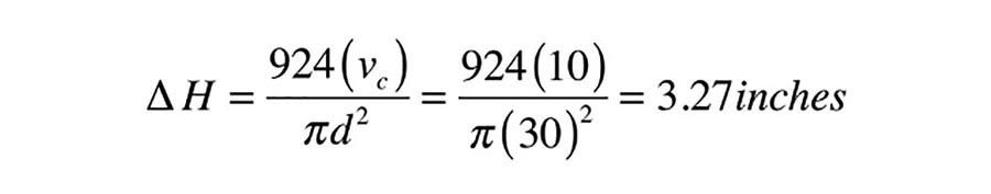
Formula 3 can be rearranged and used to calculate the drop in water level (∆H) within the cylindrical tank when the collector circulator is operating.
Formula 3 (rearranged):
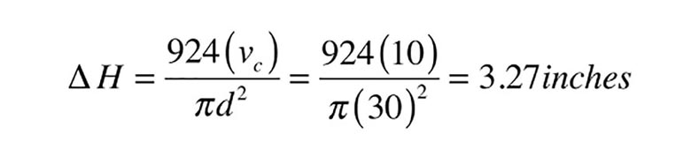
Where:
∆H = Change in water level within tank when collector is on vs. off (inches)
d = Diameter of tank (inches)
vc = Volume of collector array + collector piping above static water level (gallons)
In the previous example, where the collector array and associated “drainable” piping had a total volume of 10 gal., the drop in water level when the collector circulator is on would be:
Beyond minimums
The formulas above rely on the ideal gas law, as well as assumptions such as inferring that all air and water in the system has the same temperature at the same time. They also assume the absolute vapor pressure of the water in the tank is relatively low compared to the absolute air pressure and does not include the effect of partial pressures. Conservative design practice would use the results of these calculations as guidelines to which safety factors in the form of greater internal air volume and reduced pressure relief-valve ratings can be applied.
This article was originally titled “Room to grow (Part 2)” in the December 2017 print edition of PM Engineer.
For the full pdf of this article, read here.

