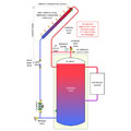
Figure 1.
One of the simplest and most reliable configurations for a solar thermal combisystem makes use of drainback freeze protection. The concept is really simple: Drain the water out of the collectors and exposed piping whenever the collector circulator is not operating. This includes nighttime, low sun conditions as well as during a power failure or if the maximum-allowed tank temperature condition occurs during sunny conditions. The latter two conditions allow the collectors to “dry stagnate” without concern over degradation of the antifreeze fluids used in other types of systems.
Although there are several ways to configure components for drainback freeze protection, my favorite approach uses the top of the storage tank to hold the drainback volume and accommodate the expansion of water within the system when it is heated. This eliminates the need for a conventional expansion tank. An example of this configuration is shown inFigure 1.
This article discusses the specifics of sizing the air space at the top of the tank. The formulas given are based on vertically oriented cylindrical pressure vessels.

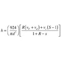
Figure 2.
Defining The Extremes
To determine the required space at the top of the tank, one must establish criteria for the changes in temperature, pressure and volume of the captive air that will occur between two limiting conditions.One of those limiting conditions is when the system is filled with cold water and the collector circulator is not operating. All water in the system (e.g., that which will eventually be in the collectors as well as that in the tank and distribution system) is assumed to be at some initial (relatively cool) temperature such as 60º F. The air at the top of the tank is also assumed to be at the same temperature.
This state establishes the static water level in the system. The distance from the top of the tank down to the water level is designed as (h). The pressure of the air at the top of the tank and in the empty collector array and collector array piping is assumed to be at some initial pressure. It could be atmospheric pressure or a slightly higher pressure.
The other limiting condition occurs when all water and air in the system are at some maximum allowable temperature (180º F for example). Under this condition, the air at the top of the tank cannot exceed some limiting pressure. The limiting pressure assumed in the formulas to follow is the rated opening pressure of the pressure relief valve at the top of the tank.
These two limiting conditions are shown inFigure 2.
Formula 1
Formula 1

Formula 2
Formula 3
Formula 4
h = MINIMUM height of cylindrically shaped air space required at top of tank (inches)
d = tank diameter (inches)
vT = volume of entire tank (water and air space at top in gallons)
vd = volume of water in distribution system (gallons)
vc = volume of collector array + collector piping above static water level (gallons)
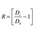
Dc = density of “cold” water when system is filled and pressurized (lb/ft3)
Dh = density of water in system at maximum temperature (lb/ft3)
pi = initial air pressure in tank when water is cool (psi gauge)
pRV = opening pressure of pressure relief valve (psi gauge)
Tmax = maximum temperature of water and air in system (ºF)
Ti =initial temperature of water and air in system (ºF)
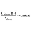
These formulas are derived from the ideal gas law. This law, which is fundamental to thermodynamics, is a combination of Boyle’s Law and Charles’s Law. Mathematically it can be expressed as Formula 4.
Formula 4
In other words, this formula states that the absolute pressure of a quantity of air multiplied by its volume and divided by its absolute temperature remains a constant.
So how did the relatively simple Formula 4 spawn off the three more complex formulas? It comes from defining specific constraints for the tank (in this case a vertical cylinder with flat ends) along with the initial and final conditions for the captive air volume in the system, and making sure all pressures and temperatures are expressed as absolute temperatures and absolute pressures (e.g., absolute temperature = ºF + 460; absolute pressure = gauge pressure + 14.7).
Putting In The Numbers
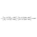
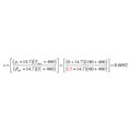
Here’s an example of how to use these formulas, assuming you are sizing up a tank for a drainback system. The tank you’ve selected has flat ends, a volume of 250 gallons and an internal diameter of 30 inches. The system is filled with water at 60º F, and the air space at the top is left at atmospheric pressure (e.g., gauge pressure = 0). The distribution system (exclusive of the storage tank and collector subsystem) contains 50 gallons of water. The maximum temperature condition assumes that all water and captive air in the system reaches 180º F. The latter is a conservative assumption because it is unlikely the entire distribution system will reach this high temperature. A 30 psi-rated pressure relief valve is installed at the top of the tank. What is the minimum vertical dimension of the air space at the top of the tank to accommodate expansion?Solution: There is sufficient information given to immediately evaluate Formula 2 (see right).
Formula 5
Formula 5
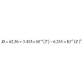
D = density of water (lb/ft3)
T = water temperature (°F)
At 60ºF the density of water is: Dc = 62.4 lb/ft3
At 180 ºF the density of water is: Dh = 60.5 lb/ft3
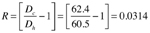
Formula 3 can now be used to find R:

Formula 6
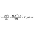
The actual volume of the expansion space within the tank can be determined using Formula 6.
Formula 6
Where:
v = volume of the expansion space within the tank (gallons)
d = tank diameter (inches)
h = minimum height of cylindrical air space (inches)
If you’re familiar with sizing nondiaphragm-type expansion tanks, this volume probably seems a bit low for a system with almost 300 gallons of water being heated from 60° F to 180º F. However, keep in mind that the volume of the collectors and the piping to and from them is also filled with air and thus acting as an expansion space. If the collector circulator is running, this air volume is just moved from the collector into the storage tank. For the previous example this adds another 10 gallons to the system’s air volume, making the total expansion air volume around 15.5 gallons.
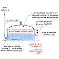
Figure 3.
Keep It Conservative
Also keep in mind that (h) is the minimum air space height required. You can always opt to be a bit more conservative and include more air space or change the limiting constraints. For example, I often suggest subtracting 5 psi from the rated pressure of the relief valve as the maximum pressure the valve should reach with assurance it will not “dribble.”Another conservative assumption would be to assume that the air volume within the dished head at the top of the tank is simply extra expansion space as shown inFigure 3.
Anything that increases the air volume in the system relative to the water volume will reduce the pressure fluctuation as the system heats up and cools down.
While you’re still looking at Figure 3, consider the placement of the tank inlet connection from the collector array. I suggest it be a couple of inches below the water level in the tank when the circulator is on. This helps reduce the splashing noise as water enters the tank. The flow enters the tank horizontally to help preserve temperature stratification.

Formula 6

∆H = change in water level within tank when collector is on vs. off (inches)
d = diameter of tank (inches)
vc = volume of collector array + collector piping above static water level (gallons)
For the previous example, in which the collector array and its piping had a total volume of 10 gallons, the drop in water level when the collector circulator is running would be:
Also, be sure the piping connection leading to the distribution system is at least a couple of inches below the water level in the tank when the collector circulator is operating.
Exercising The Formulas
Here’s a final example to show how things can change with different tank geometry and relief valve settings. Assume the tank is only 22 inches in diameter but still has a total volume of 250 gallons. The array collector piping above the static water level has a total volume of 5 gallons. As in the previous example, the distribution system has a volume of 50 gallons. Assume the pressure-relief valve is rated at 15 psi, and that the same minimum and maximum water temperatures (60° F and 180º F) remain in effect.The value of S is now:


This is a substantial change in the minimum air space height. It is due to a decrease in tank diameter, a decrease in the pressure relief valve setting and a smaller collector volume.
The combined volume of the air space in the tank and the collector array plus collector piping is now about 22.7 gallons.
Use the formulas and data given in this article, perhaps as a spreadsheet, to determine the minimum required height of the air space at the top of the drainback tank. Then, add at least an inch or two to the required height as a further safety margin. Although the mathematics may look a bit messy, the underlying physics of drainback systems are simple, reliable and efficient.


