All solar thermal systems that use drainback freeze protection require a space to accommodate the water volume that drains from the collector array and its associated piping. That space also is used to absorb the increased volume of water as it is heated within the system.
When the system uses a non-pressurized thermal storage tank, the air space above the water level in the tank can handle this function. The required depth of this space depends upon several factors including:
- The dimensions of the thermal storage tank;
- The total water volume in the system;
- The maximum overall temperature change of that water;
- The volume of the collector array; and
- The volume of the piping which drains along with the collectors.
Formula 1 can be used to estimate the change in height of water within an open storage tank based on these factors.
Formula 1

Formula 1 can be used to estimate the change in height of water within an open storage tank based on these factors.
Where:
∆H = the increase in water level due to expansion of system water (inches);
Vc = volume of the collector array (gallons);
Vep = volume of all piping to/from collector array that drains (gallons);
Vwt = volume of water in thermal storage at cold fill (gallons);
Vd = volume of water in distribution system (gallons);
Dc = density of water at cold fill conditions (lb/ft3);
DH = density of water at maximum tank temperature (lb/ft3); and
At = cross sectional area of storage tank (in2).
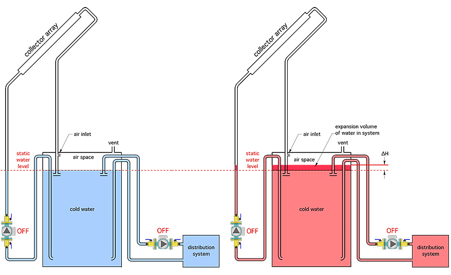
Figure 1 shows the change in water level due to heating.

Figure 1 shows the change in water level due to heating.
Here’s an example: A non-pressurized cylindrical thermal storage tank has liner shell measuring 60 in. tall and 48 in. in diameter. It is filled with cold (60º F) water to within 6 in. of the top of the liner. The space heating distribution system is directly connected to the tank and holds an additional 50 gal. of water. The drainback solar array contains five collectors with a volume of 1.2 gal. each. There is 100 ft. of 3/4-in. copper tubing that must drain back to the thermal storage tank at the end of each collection cycle. The system controls are configured so that the maximum temperature the thermal storage tank can reach is 180º. Determine the change in height of the water in the tank when the collector array is drained and the water is at its maximum temperature.
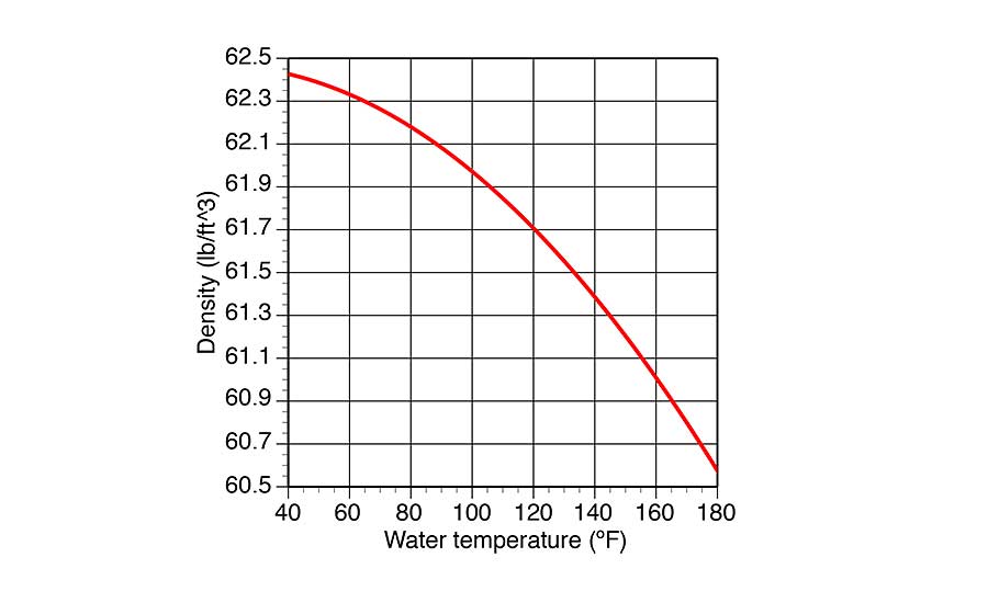
Solution: The density of water at both 60º and 180º is required. These densities can be estimated from Figure 2.

The density of water at both 60º and 180º is required. These densities can be estimated from Figure 2.
D60 = 62.4 lb/ft3
D180 = 60.3 lb/ft3
Formula 1 also requires the cross-sectional area of the tank. In this case the tank is cylindrical, and thus has a cross-sectional area of:

Formula 1 also requires the cross-sectional area of the tank. In this case the tank is cylindrical.
This data, and the remaining values can now be processed through Formula 1:
 This data, and the remaining values can now be processed through Formula.
The estimated change in water level of 2.9 in. is conservative. It assumes that all the water in the system reaches the same maximum temperature of 180º at the same time. This is virtually impossible because of stratification within the tank and the temperature drop that must occur in any distribution system that is dissipating heat.
In systems that link the space heating distribution system to the storage tank using a heat exchanger, the volume of water in the distribution system, represented as (vd) in Formula 1, would be zero. This will reduce the change in water level.
Knowing the maximum change in water level due to expansion informs the designer on how high to locate an air inlet tee, which allows air back into the collector piping when the collector circulator turns off. It also informs the designer where to locate any bulkhead fittings through the tank wall and that need to remain above the flooded volume of the tank.
The static water level in the tank when filled with cold water is the benchmark elevation. Prudence dictates any hardware that is not supposed to be immersed in the tank water is some margin above the maximum (system water at maximum temperature) level. I suggest at least a 2-in. margin.
Things get a bit more complicated when the drainback system uses a closed/pressurized tank. We’ll get into that in a future Renewable Heating Design column.
This article was originally titled “Room to grow” in the November 2017 print edition of PM Engineer.
To read the full article in pdf form, see here.


