
Welcome to the first of a series of newPM Engineer,columns entitled Solar Design Notebook. The intent of this series is to bring readers technical information on the design of active solar thermal systems for water heating and space heating.
Interest in the use of solar energy in North America is growing rapidly. For some, that interest is driven by the ecological benefits of using solar energy. For others, it’s driven by the desire to move North America closer to energy independence. For still others, the interest is based on displacing increasingly expensive fossil fuels.
All these incentives are valid. However, one thing they have in common is that none of them can be realized without the ability to create efficient, reliable and long-lasting solar thermal systems - and that’s where this column fits in. Here, we’ll be discussing design details for solar thermal systems that allow them to perform as expected, and provide long service lives.
This column is a new direction forPM Engineer. In an effort to ensure it meets that goal, we invite you to e-mail us with your suggestions on future topics and comments.
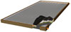
Figure 1. Image courtesy of Solarskies, Inc.
Worldwide, there are hundreds of different manufacturers offering solar collectors. Although their design details vary, fundamentally they fit into two categories:
This month we’ll look at the construction of both types of collectors, and compare their thermal efficiencies.
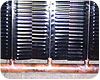
Figure 2. Image courtesy of Solarskies, Inc.
Flat Out
A cut-away of a typical flat plate solar collector is shown inFigure 1. The heart of the collector is its absorber plate. Its function is to intercept as much incoming solar radiation as possible, convert it to thermal energy, and transfer that energy to the fluid passing through it. It is, in simple terms, a radiation-to-fluid heat exchanger.Most absorber plates are made from copper sheet bonded to copper tube. The bond can be formed using forge welding, ultrasonic welding, mechanical clamping or soldering. A common fabrication uses forge welding to bond a nominal 3/8-inch tube to a strip of copper about 5 inches wide. These tube/sheet assemblies are placed side by side, and the ends of the tubes are brazed to copper headers, as shown inFigure 2.
The upper surface of the absorber plate is electroplated with a “selective surface.” This coating provides high absorption of incoming solar radiation and reduces radiant heat loss from the plate.
The absorber plate is usually housed in an aluminum enclosure with side and rear insulation. The glazing on the enclosure is tempered “low iron” glass, which allows maximum transmission of the incoming solar radiation.
A cross-section of a typical flat plate collector is shown inFigure 3. A residential installation of two flat plate collectors for domestic water heating is shown inFigure 4.
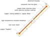
Figure 3. Image courtesy of Caleffi North America
Wonder Tubes
All solar collectors lose heat to their surroundings. The lower this heat loss, the more useable heat the collector delivers. Although the selective surface coating on the absorber plate reduces radiant heat loss to a minimum, the air inside a flat plate collector readily convects heat from the warm absorber plate to the cool glazing. Minimizing this convective heat loss is the design objective of an evacuated tube collector.As in flat plate collectors, the absorber strip of an evacuated tube is made from a narrow copper strip welded to copper tube. The upper surface of the strip is plated with a selective surface.
In some evacuated tubes the absorber strip is inserted into a glass cylinder, and both ends are closed. Air within the cylinder is removed (e.g., evacuated), much like air is removed from an incandescent light bulb during manufacturing. The absence of air around the absorber strip reduces convective heat loss from the absorber strip to the glass tube to almost zero.
Other evacuated tube collectors use two concentric glass tubes to enclose the absorber strip. The vacuum exists between the inner and outer tubes, and again greatly reduces any convective heat losses.
The lack of convective heat loss allows the absorber strip in an evacuated tube collector to attain significantly higher stagnation (no flow) temperatures compared to the absorber plate in a flat plate collector.

Figure 4. Image courtesy of Solarskies, Inc.
Heat is conducted from the condenser into an antifreeze solution flowing through the manifold. This antifreeze solution carries heat to the remainder of the system. When the working fluid releases heat, it condenses to a liquid and trickles back to the bottom of the tube ready to repeat the cycle. Evacuated tube collectors typically require a minimum slope of 25 degrees above horizontal for this passive thermodynamic process to operate properly.

Figure 5. Image courtesy of Viessmann Manufacturing
Figure 6shows a typical evacuated tube collector consisting of several tubes joined to a common manifold.

Figure 6. Image courtesy of Viessmann Manufacturing
So Which is Better?
Like most answers from engineers, I’ll start the answer with “It depends.” Indeed, it does depends on several factors, including:The next Solar Design Notebook column will discuss how flat plate and evacuated tube collectors compare from a thermal perspective.


