
As interest and incentives build to transition space heating and domestic water heating systems away from fossil fuels and toward electricity, a somewhat predictable but only marginally quantified problem is developing. Two words describe it: Peak demand.
Properly sized air-to-water heat pumps can provide the majority of the space heating energy buildings require on a seasonal basis. Where the problem develops is on those few days (or even a few hours) when outdoor temperatures are at their lowest. This is when the heating capacity of any air-source heat pump bottoms out. It’s also when the typical electric resistance auxiliary heat often combined with air-source heat pumps kicks into high gear.
Recent work on the issue of peak demand as it pertains to New York State’s “Climate Leadership and Community Protection Act” (CLCPA) goals projects that somewhere around 2033, the traditional “summer peaking” situation that occurs when the electrical power demand of the state is considered as a whole, will change to a “winter peaking” situation as shown in Figure 1.
FIGURE 1
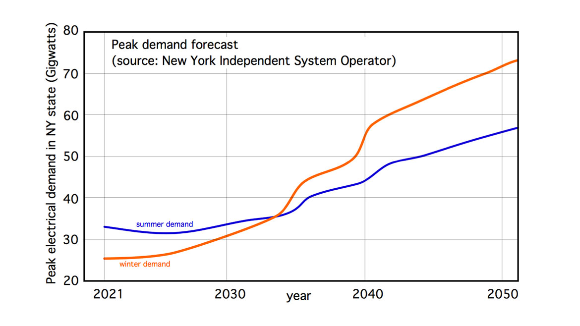
Furthermore, by 2050, peak demand (e.g., the required rate of energy delivery, not the required amount of energy) in just New York state could reach 73 Gigawatts (that’s 73,000,000,000 watts). I suspect that similar issues will develop in other states with cold winter climates, and aggressive plans to eliminate fossil fuels.
This spike in demand wouldn’t be needed for long, in some cases only a few hours per year. But when it’s needed, it is needed, and utilities, by law, must have ample reserve capacity to meet it.
Peak generation capacity is also expensive, significantly higher than costs associated with baseload electrical generation. One estimate puts it this way: If the 100 hours of peak electrical demand could be flattened, the long-term avoided costs would be between one billion and two billion dollars — and that’s just for New York state.
The road ahead
The need to “level out” the electrical power demand curve is not something that just recently came to light. Utilities have been working on various methods for shifting peak loads to low-demand periods for several decades. Those methods include time-of-use rates, moment-by-moment pricing (referred to as “frequency regulation’), interruptible service agreements, installation of large-capacity battery banks, and pumped water storage at hydroelectric generating facilities.
All of these load management tools create opportunities that informed system designers can leverage on the customer side of the meter to benefit their clients as well as the utility. When it comes the heating and cooling, the hydronics playbook holds the potential to achieve several “win/win” scenarios.
One option is thermal energy storage. It could be in the form of insulated thermal storage tanks filled with water that are charged with heat during off-peak hours. Depending on the on-peak/off-peak kWh cost ratio, it may be feasible to charge the thermal storage tank to relatively high temperatures (190-200° F) using electric resistance heating elements or “high temperature” air-to-water heat pumps with cascading refrigeration systems, CO2 refrigerant, or propane as a refrigerant (assuming that U.S. regulators can see the value in the latter).
The use of relatively large thermal storage tanks to stabilize the differences between heat generation and heat demand is not new. Such tanks have been used for decades in systems supplied by solar thermal collectors, wood-based biomass boilers and electric boilers operating on off-peak electrical rates.
From a practical standpoint, storing significant amounts of thermal energy using water in tanks presents several cost and logistic challenges. The tanks are large, heavy and expensive. Nearly all mechanical codes require tanks larger than 119 gallons, and capable of being pressurized, to meet Section VIII of the ASME pressure vessel code, which definitely adds to their cost. The current situation with steel prices only exacerbates an already costly option. The logistics of transporting and installing multi-hundred-gallon tanks in homes or light commercial buildings are also arduous.
Solid thinking
Another possibility is “solid” thermal storage in the form of a heated slab, or solid thermal mass under a heated slab. One concept for the latter is shown in Figure 2.
FIGURE 2
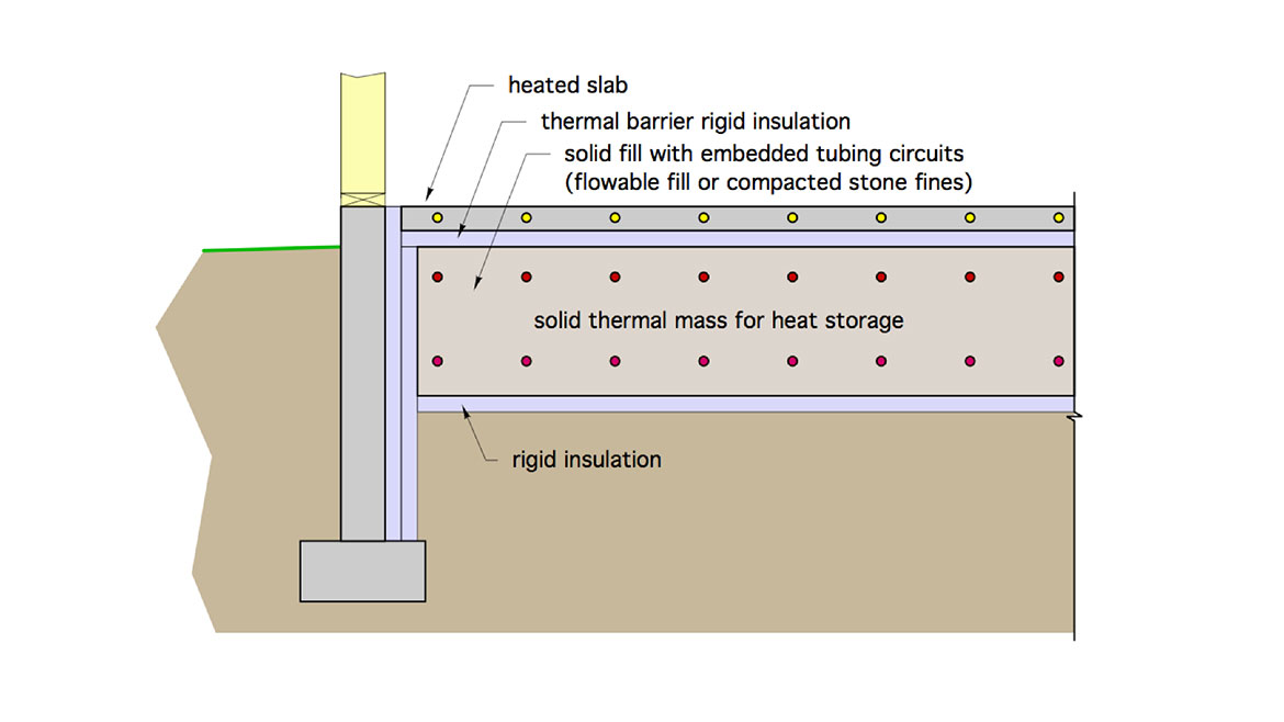
The upper slab contains embedded tubing and serves as the heat emitter for the space. It’s separated from the lower thermal mass by a layer of rigid insulation. The latter provides a high degree of thermal isolation between the lower mass and the heating needs of the space.
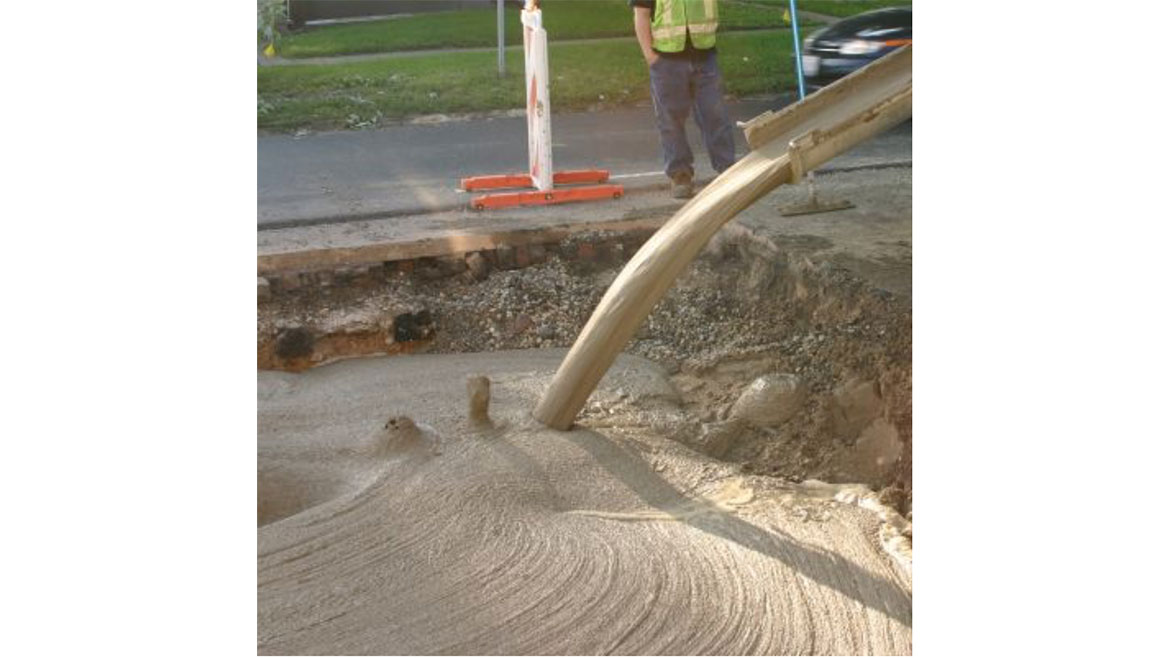
The lower solid thermal mass could be a material such as compacted stone dust, or “flowable fill.” The latter has been used for filling large voids in sub-grades for several years. It’s typically a mixture of Portland cement, fine aggregate (sand), and fly ash or slag. It has acceptable load-bearing strength for use under slabs, (about 150 psi compressive strength) but far less than that of structural concretes (typically 3,000-4,000 psi compressive strength). It’s pumped from a standard concrete delivery truck into the void to be filled and is self-compacting and self-leveling, as seen in Figure 3.
FIGURE 3
The material used for solid thermal storage needs to have reasonably good thermal conductivity as well as good heat capacity. Sand (without a binder material) is not a good choice for this application because of its relatively low thermal conductivity due to limited contact area between grains.
Embedded tubing within the lower thermal mass carries water heated by an electrically-operated heat source such as an electric boiler, air-to-water heat pump, or geothermal water-to-water heat pump. This flow occurs when off-peak, or other low-cost electrical rates are in effect. This allows heat to be stored without concern about overheating the conditioned space.
When on-peak electrical rates are in effect the preferred operating mode would be to shuttle heat from the lower thermal mass to the heated slab. If necessary, the heat source(s) could also be configured to shuttle heat directly to the upper slab to maintain the desired comfort level.
The exact proportions of the various elements in this approach remain to be determined, most likely based on detailed computer simulation as a starting point, followed by proof-of-concept testing.
Solid thermal mass holds some appealing characteristics over large (multi-hundred gallon) water storage tanks for this type of application:
- It’s likely to be less expensive per kWh or MMBtu of thermal storage capacity;
- It eliminates the logistics of placing a large thermal storage tank in a typical building;
- When one or more monobloc air-to-water heat pumps serve as the heat source, antifreeze is typically required in the system. The tubing circuits embedded in the solid thermal mass would contain far less volume than an equivalent thermal storage tank, and thus reduce the amount of antifreeze needed. Lower system volume also implies a smaller expansion tank;
- Depending on the thermal characteristics and dimensions of the solid thermal storage, it could likely store a given amount of heat at lower temperatures relative to an economically justifiable water storage tank. Lower storage temperatures reduce thermal losses. They would also allow air-to-water heat pumps, which are currently limited to about 130° F leaving water temperature, to contribute a higher percentage of stored energy, relative to systems that count on very high storage temperatures (190-200° F);
- Any concerns for corrosion or leaks associated with water storage tanks are eliminated; and
- The building space required for water-based thermal storage is no longer needed.
Hydronics playbook
Figure 4 shows a system piping concept that could shuttle heat into and out of the solid thermal mass.
FIGURE 4
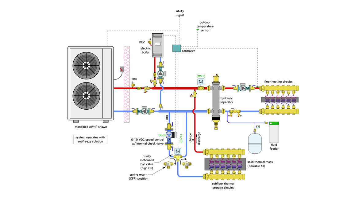
Heat is generated by the air-to-water heat pump or the electric boiler. The water temperature required as well as the electric rate in effect at the time would determine which heat source is preferable. It’s also possible, under certain circumstances, to operate both heat sources simultaneously. Two heat sources also provide redundancy. If one heat source is down for service the other can still provide some heat input to the system.
Think about it
The piping shown in Figure 4 is relatively simple, but it allows a variety of operating modes, including:
- Mode 1: Heat Pump supplies floor heating directly;
- Mode 2: Electric Boiler supplies floor heating directly;
- Mode 3: Heat pump supplies heat to thermal storage, but with space heating override;
- Mode 4: Electric boiler supplies heat to thermal storage, but with space heating override; and
- Mode 5: Thermal storage supplies floor heating using outdoor reset control.
Look over the components in Figure 4 and see if you can figure out what they do and how they operate in all of the above modes. If you’re not sure — no worries. I’ll describe each of these operating modes in next month’s column.


