
Nearly all systems using cordwood gasification or pellet-fueled boilers perform best when the system includes a thermal storage tank. That tank absorbs heat during the boiler’s typical 2 to 4 hour burn-cycle, allowing the boiler to remain at or close to steady state conditions. This increases thermal efficiency and significantly reduces particulate emissions.
A thermal storage guideline for pellet-fueled boilers is 2 gallons of water per 1,000 Btu/h of the boiler’s rated output. For cordwood gasification boilers, the guideline is 130 gallons of water per cubic foot of the boiler’s primary combustion chamber. When these guidelines are applied, even residential systems require substantial amounts of thermal storage.
The approach that I prefer — whenever possible — is using a single pressure-rated thermal storage tank, such as the 350 gallon unit shown in Figure 1.
FIGURE 1:

Tanks intended to operate under pressure, and having volumes over 119 gallons, typically must be listed and labelled under the ASME Section VIII pressure vessel code to conform with most mechanical codes.
The logistics of moving a large steel tank into a mechanical room, especially in a residential structure can be formidable — if not impossible. Constraints such as weight, door width and ceiling height can all be limiting factors.
In these situations, one alternative is use of a multiple tank system to achieve the required volume and avoid the constraints of a single large tank.
Before making a decision
Although it’s possible to use two or more thermal storage tanks to achieve the desired total storage volume, there are “consequences” associated with that approach. One is the surface area to volume ratio of a multiple tank array is often much higher than that of a single tank of the same total volume.
For example, Figure 2 shows a comparison between four 119 gallon tanks versus a single tank of the same total volume 476 gallons. To keep the math simple, the tanks are assumed to be flat-ended cylinders with a height-to-diameter ratio of 3.
FIGURE 2:

The four smaller tanks, combined, have 59% more surface area per gallon of volume compared to the single large tank. Assuming that all the tanks would have the same temperature profiles and insulation, the four smaller tanks would experience 59% higher standby heat loss, not to mention higher heat loss from the piping required to connect the small tanks together.
It’s also likely that the cost of the array of smaller tanks, on a dollars per gallon of storage basis, will be higher than that of the single large tank. The additional piping costs in a residential project are easily several hundred dollars, and perhaps even multiple thousands of dollars in a commercial application.
It’s also important to consider the “footprint” of the multiple tanks. They are definitely going to require more room in the mechanical room.
Piping configurations
If the situation warrants use of multiple thermal storage tanks, there are several options for piping. Two common approaches would be parallel-direct return, shown in Figure 3a, and parallel-reverse return, shown in Figure 3b.
FIGURE 3A:
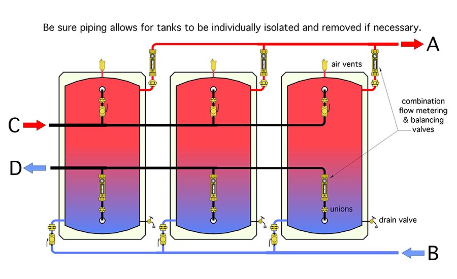
FIGURE 3B: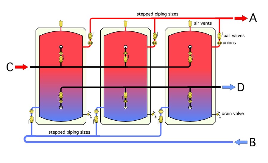
The parallel-direct return system uses less piping compared to the parallel-reverse return scenario. However, it is imperative to use balancing valves with the direct return approach to keep the total flow balanced equally between the tanks. The balancing valves can also provide isolation of the individual tanks if ever needed.
The parallel-reverse return piping will help keep the flow rate between the tanks closer to equal, but I want to stress that “closer” doesn’t mean “equal.” Balancing valves should still be used with reverse return piping.
Accessibility
The probability of having to remove one or more of the tanks in a multiple tank array that’s part of a properly designed and maintained system is quite small. Still, a design decision must be made as to whether any tank in the array should be capable of being isolated and removed, if necessary, and what the consequences of this decision entail.
If the decision is to provide for possible isolation and replacement of any tank in the array, it’s important to make access as easy as possible. Don’t locate piping in areas that require more than very minor disassembly in the event a tank has to be pulled.
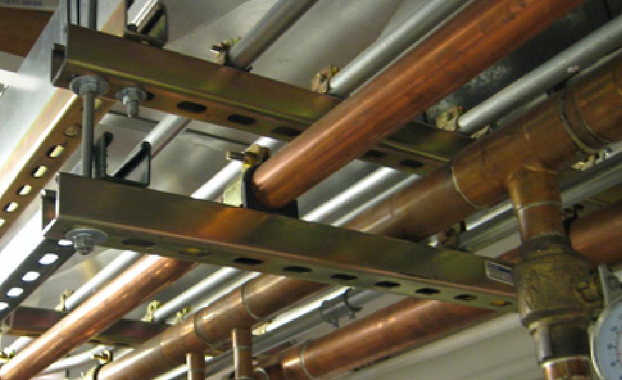
One approach is to locate the piping behind the tanks, as represented in Figure 4. Another is to locate the piping on strut rails or other hangers above the tanks, as shown in Figure 5.
FIGURE 4:
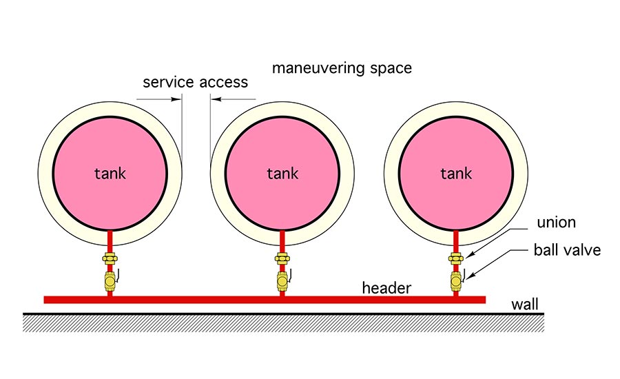
FIGURE 5:
Be sure to use a union and full port ball valve wherever a pipe connects to a tank. Consider use of reinforced hoses in locations where rigid piping would have to be disassembled to maneuver a tank out of the array.
Figure 6 shows an array of three 600 gallon tanks where these consideration were not well planned.
FIGURE 6:
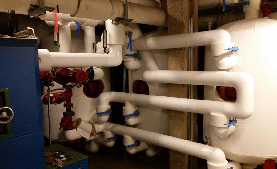
Put yourself in the position of a service or maintenance person who might have to deal with a leak at one of the piping connections to these tanks. Even worse, image that one of the two tanks in the background of this photo might someday have to be replaced. Given the wall behind these tanks, let’s just say that they’re not likely to come out in one piece.
More to come
There are other piping strategies for multiple thermal storage tanks that are quite a bit simpler than what we’ve looked at some far. We’ll get into them more next month.


