
Geothermal (a.k.a. ground-source) heat-pump systems continue to be a popular topic in HVAC discussions. Many state and federal agencies are now offering generous incentives for installation of geothermal heat pumps in both residential and commercial applications.
Engineers involved with hydronic systems should be familiar with what geothermal systems have to offer. Specifically, how water-to-water geothermal heat pumps can be integrated with modern hydronic heating. To properly apply them, it’s important to understand the basic thermodynamics involved.
The fundamentals: All heat pumps move heat from a material at lower temperature to a material at higher temperature. The “source” from which lower-temperature heat is taken can be just about anything. Many heat pumps extract heat from outside air and are appropriately called “air-source” heat pumps. Geothermal heat pumps extract heat from ground water or a fluid circulated through tubing buried in the ground.
Most geothermal source heat pumps operate using a standard vapor-compression refrigeration cycle. As the refrigerant moves around the cycle, it changes from vapor to liquid and vice-versa in a continuous process. When liquid refrigerant evaporates, it absorbs heat from its surroundings. Conversely, when refrigerant vapor condenses back to a liquid, it releases heat to its surroundings.
> FIGURE 1.
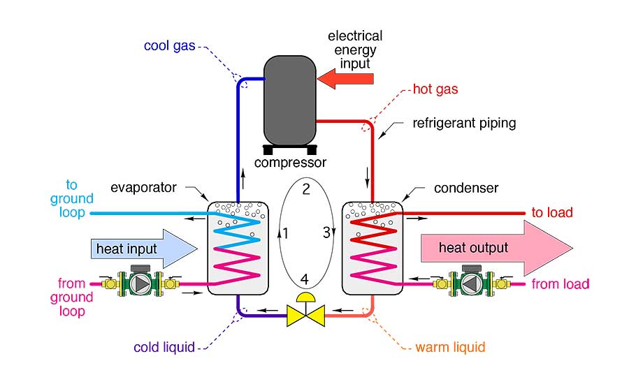
Figure 1 shows the principle components in a water-to-water heat pump, and gives the condition of the refrigerant at several locations within the system.
Liquid refrigerant enters the evaporator as a low-temperature, low-pressure liquid. It passes across the surface of copper tubing through which water or a mixture of water and antifreeze flows. Because the liquid refrigerant is several degrees colder than the water, it absorbs heat from it. The absorbed heat causes the cold refrigerant to vaporize.
The cool refrigerant gas then passes to the electrically operated compressor, where its pressure and temperature are greatly increased. The hot refrigerant gas line leaving the compressor can be quite hot (140º to 170º F).
The hot gas flows on to the condenser, where it passes across another copper coil carrying water from the hydronic distribution system. Because the refrigerant gas is warmer than the water, heat moves from the gas to the water. This causes the refrigerant to condense back to a liquid, but still remain at a relative high pressure.
Finally, the liquid refrigerant flows from the condenser to the thermal expansion valve (TXV). As it flows through this valve, its pressure is reduced and its temperature immediately drops. The refrigerant is now back to the same condition it started from at the base of the evaporator. It’s ready to repeat this cycle as long as the compressor is running.
Although the specific components used in water-to-water heat pumps vary from one manufacturer to another, the goal is always the same: To move heat from the low-temperature “source” to the higher temperature “load” using as little electrical energy as possible.
Energy in = Energy out: Geothermal water-to-water heat pumps live by the first law of thermodynamics. Simply stated: Under steady-state operation, the total energy flowing into a heat pump equals the total energy flowing out of that heat pump.
Some energy comes in as low temperature heat from the “source” (i.e. ground loop, ground water, etc). Energy also enters the heat pump in the form of electricity to run the compressor. These two energy input streams always add together to form the energy output stream, which is imparted to the stream of water flowing through the heat pump’s condenser.
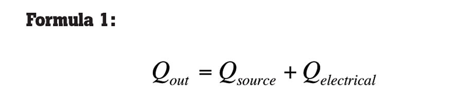
Mathematically this energy balance can be written as Formula 1:
> Formula 1:
Where:
Qout = Rate of heat output from heat pump condenser (Btu/h).
Qsource = Rate of heat absorption from low-temperature source (Btu/h).
Qelectrical = Rate of electrical energy input to operate heat pump (Btu/h).
> FIGURE 2.
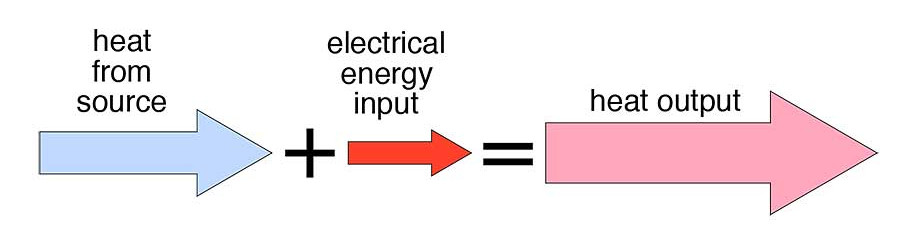
You can visualize these energy streams as shown in Figure 2.
How’s it running? When dealing with boilers, we often discuss thermal efficiency. It’s the ratio of the heat output divided by the heating value of the fuel being consumed. The higher the efficiency, the better, but no combustion-based boiler will ever meet or exceed 100% thermal efficiency.
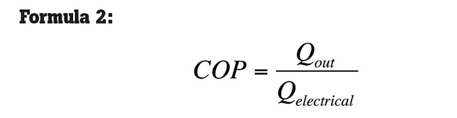
With heat pumps, the performance indicator is called coefficient of performance (or COP for short). COP is the ratio of the heat output rate from the heat pump divided by the electrical energy input rate to operate the heat pump. Mathematically it’s just a ratio as given by Formula 2:
> Formula 2:
When both the top and bottom of the fraction have the same units, they cancel out to give a pure number. Since we usually measure electrical power in watts rather than Btu/h, we can modify Formula 2 so watts can be entered and then converted to Btu/h. The result of this formula is a pure number (e.g. it has no units).
> Formula 3:
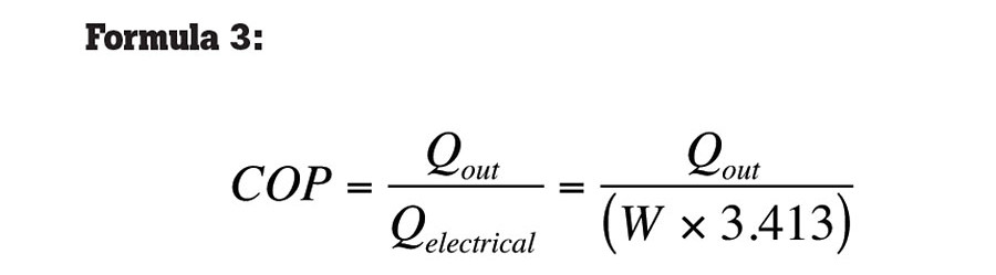
Where:
Qout = Rate of heat output from heat pump condenser (Btu/h).
W = Watts of electrical power entering heat pump.
The COP of a water-to-water heat pump is very dependent on the current operating conditions (e.g., the entering source water temperature and its flow rates, as well as the temperature of water returning to the heat pump from the load). Figure 3 shows a plot of the listed COP data for one specific water-to-water heat pump. Notice the COP varies significantly as a function of both entering source water temperature and entering load water temperature (ELWT).
> FIGURE 3.
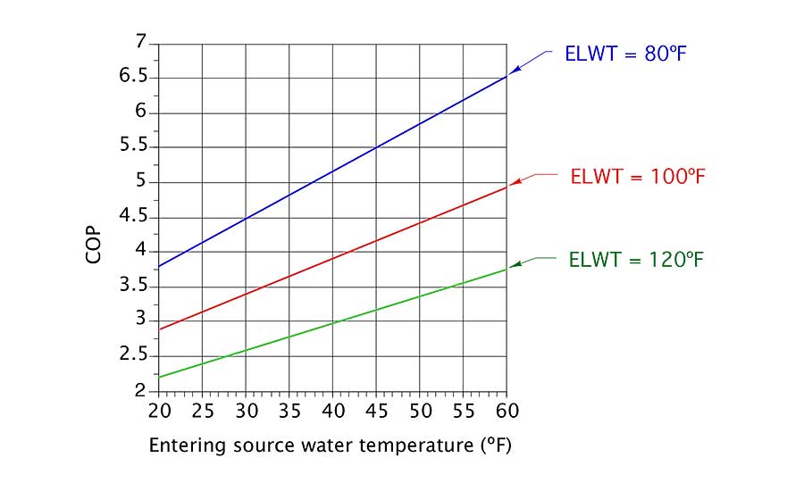
The heat pump’s COP drops quickly as the temperature of the source water from which heat is extracted decreases. It also drops as the temperature at which the load operated increases. Thus, low-temperature heating loads like heated floor slabs with low-resistance coverings, or no coverings, are a good match for water-to-water GSHP systems.
It’s also important to understand that listed COP data for water-to-water heat pumps may or may not include an allowance for the electrical power required to operate circulators that product flow through both the evaporator and condenser. If the COP data is based on ANSI/AHRI/ASHRAE/ISO Standard 13256-2, it typically includes an allowance for an assumed power input for the circulator on the source side of the heat pump.
However, the calculation used in this standard does not necessarily yield the same circulator power requirement as the actual circulator(s) used. It also doesn’t include any power allowance for the circulator used on the load side of a water-to-water heat pump. If you want to calculate a “net” COP of the heat pump and both circulators that must be on whenever the heat pump is operating, add the wattage of both circulators to the power demand of the heat pump itself, and use that total power in the denominator of Formula 3.
Any 2 out of 3: If any two of the three energy flows present in an operating heat pump are known, the third energy flow can be determined by simple addition or subtraction. For example: If you need to know the heat output of a geothermal heat pump, you could determine the rate of heat coming to the heat pump from the source water, and add this to the rate of electrical energy input to operate the unit. For a water-to-water geothermal heat pump, you also could measure the flow rate and temperature change of water as it passes through the condenser, and directly calculate the rate of heat delivery using Formula 4:
> Formula 4:
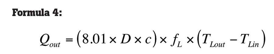
Where:
D = Density of fluid passing through condenser (lb/ft3).
c = Specific heat of fluid passing though condenser (Btu/lb/ºF).
fL = Flow rate of fluid passing through condenser (gpm).
Tlout = Temperature of fluid leaving condenser (ºF).
Tlin = Temperature of fluid entering condenser (ºF).
Because most geothermal heat pumps are water-to-air units rather than water-to-water, it’s customary to combine the rate of heat input at the evaporator with the rate of electrical energy input to obtain the heat output. Figure 4 shows the necessary operating conditions that need to be measured to use this method. It also gives the formulas necessary to convert these measurements into a heat output number.
> FIGURE 4.
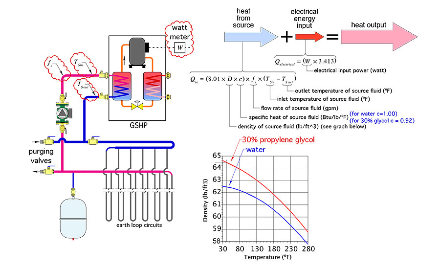
The formulas require the density and specific heat of the fluid flowing through the evaporator. These can be read from the graph in Figure 4. Use the average of the evaporator inlet and outlet temperature to estimate density. The specific heat of water and glycol-based solutions doesn’t vary much within the narrow temperature range at which it is used in these systems. Thus, it can be treated as a constant (c for water =1 Btu/lb/º F, and c for a 30% solution of propylene glycol is 0.92 Btu/lb/º F).
If you have a wattmeter, just take the measurement. If you don’t have such an instrument, you can use a standard multimeter along with multiplication to get an estimate of input wattage. Measure the voltage and current to the heat pump, then convert to using Formula 5:
> Formula 5:
The value 0.95 represents the power factor of a typical scroll compressor as used in most modern heat pumps.
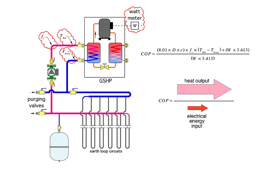
You can also use this measured data to calculate the COP of the heat pump as shown in Figure 5.
> FIGURE 5.
Getting accurate temperature measurements (within +/-0.1 º F) is possible with modern profession instruments that use strap-on RTD, thermistor or thermocouple probes. Don’t rely on an infrared gun to “shoot” these temperatures. They aren’t accurate enough for the narrow temperature range being measured.
Getting flow rates is usually more of a challenge than getting accurate temperatures. If the system happens to have an accurate flow meter installed in either the earth loop or hydronic distribution system, getting a flow reading is easy. Remember, you only need flow on one side of a water-to-water heat pump to use the formulas given above.
> FIGURE 6.
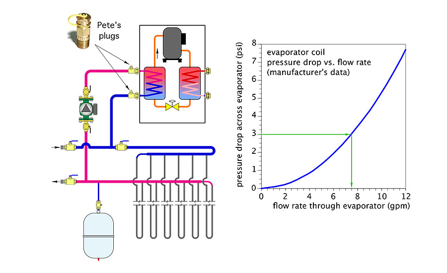
An “indirect” way of estimating flow rate makes use of special fittings called “Pete’s Plugs.” These devices, shown in Figure 6, are commonly installed at the source flow connections on the evaporator. They allow a narrow temperature probe or pressure probe to be temporarily inserted through a neoprene gasket. When the probe is removed, the gasket is “self-healing.” The brass cap is screwed on to prevent any drips when probes are not inserted.
Once the pressure drop across the evaporator coil is known, the corresponding flow rate can be estimated from a graph supplied by the heat pump’s manufacturer. This method is simple and relatively inexpensive, but not as accurate as reading flow directly from a quality flow meter. Still, it’s an effective technique for field-estimated performance.
> FIGURE 7.
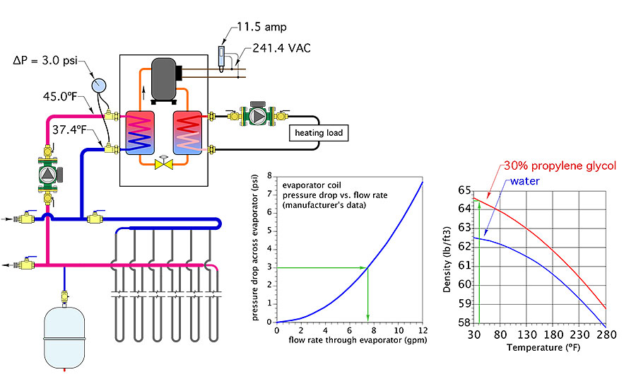
For example: A technician uses his instruments to take the temperature, differential pressure and electrical readings shown in Figure 7. He also references a manufacturer’s graph of the pressure drop across the evaporator coil as a function of flow rate. He also looks up the density of the 30% propylene glycol solution used in the earth loop, and finds it to be 64.5 lb/ft3 at an average temperature of 41º F. The specific heat of this solution is 0.92 Btu/lb/º F. Use these readings and physical properties to determine:
a. The heat output from the heat pump
b. The current COP of the heat pump
Start by calculating the electrical wattage to the heat pump:

Next, estimate the flow rate through the evaporator using the pressure drop versus flow rate curve provided by the manufacturer. For the graph in Figure 7, a pressure drop of 3.0 psi corresponds to a flow rate of 7.5 gpm.
At this point we know all the numbers necessary to calculate both heat output and COP:
The heating output is:
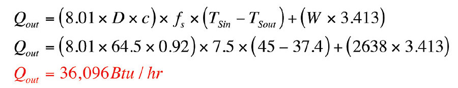
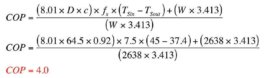
The COP is:
Do the math: These formulas and their associated data can turn the measured thermal and electrical operating characteristics of the heat pump into performance numbers. Those numbers can then be compared to manufacturer’s published performance data to verify if the unit is operating reasonably close to its rated performance. Significant differences between measured performance and rated performance (under the same operating conditions) would indicate that additional diagnostics are in order. If you’re interested in applying these heat sources, you should know how to verify they are operating properly.


