


Wood gasification boilers represent the state-of-the-art when it comes to turning cordwood into heated water.
They rely on two-stage combustion where wood is heated in a primary chamber to a point where a chemical reaction called pyrolysis occurs. The pyrolitic gases released during this process are channeled into a secondary combustion chamber where they mix with jets of superheated air. The resulting combustion resembles a blowtorch both in appearance and sound (see Figure 1).
When properly operated using well-dried wood, gasification boilers can produce steady-state combustion efficiencies in the mid-80% range. The boilers’ overall cycle efficiencies (which include startup and burnout phases) are in the range of 70 to 75%. This allows them to deliver about twice the heat output from a given quantity of wood in comparison to single-stage wood burners, especially if the latter are operated for extended periods in a “smolder mode” due to a lack of concurrent heating load.
To achieve this high efficiency, wood gasification boilers need to incinerate a full charge of wood as hot and fast as possible. This usually results in heat being generated faster than it can be used by the building. In a single-stage wood burner, this condition is dealt with by reducing air flow to the combustion process. However, this is not how a wood gasification boiler should be operated. The solution is to provide water-based storage for the surplus heat.
The following formula serves as a guideline for sizing water-based thermal storage for a wood gasification boiler.
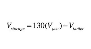
Where:
Vstorage = water storage volume (gallons);
Vpcc = volume of primary combustion chamber (ft3); and
Vboiler = water volume of boiler (gallons).
This formula is based on the possibility that a full charge of wood could be burned when there is no concurrent heating load in the building. Thus, all heat generated by the boiler would go to thermal storage. Such a situation might occur if someone fires up the boiler and the sun comes out soon after. The resulting solar heat gains might warm the building to the point where the thermostat is satisfied and there is no heat demand on the system.
If you apply Formula 1 to some of the wood gasification boilers currently available in the North American market, you are likely to find storage requirements in the range of 600 to 1000 gal. That’s serious volume and providing it requires careful planning.
Close-minded
Although there are both unpressurized and pressurized tanks that can provide thermal storage, I am a strong proponent of the latter.
Pressurized tanks eliminate heat exchangers between the steel boiler and “open” storage tank. They also eliminate a heat exchanger that would otherwise be necessary to couple an “open” storage tank to a closed pressurized distribution system. Eliminating heat exchangers reduces both complexity and installation cost. It also increases the “usefulness” of the stored heat by reducing the temperature at which the storage tank can still supply the heating load.
Closed systems also reduce the potential for oxidation-based corrosion in the system, eliminate concern over biological slime that can develop in open storage tanks and allow for positive pressure in all portions of the system.
I’ve found that pressure-rated steel tanks in the range of 200 to 400 gal. are practical from the standpoints of size, weight and handling logistics. My preference is for tanks that will fit through 36-in.-wide doors. Attaining the total storage volume calculated using Formula 1 and accommodating these other considerations usually requires two or three tanks in this size range.
There are different opinions on the best way to pipe multiple (but identical) thermal storage tanks. Some designers advocate for series piping, while others insist on parallel piping.
There are pros and cons associated with each piping approach. For example, piping tanks in series creates more head loss across the tank array. This reduces the tank array’s ability to provide hydraulic separation. Series piping might also compromise temperature stratification under certain operating conditions. Parallel piping reduces head loss, but typically requires more piping, depending on how the tank ports are arranged.
I’ve come to prefer a hybrid approach that combines attributes of both series and parallel piping as shown in Figure 2.
Adjacent tanks are “close-coupled” in parallel and piped in reverse return. However, from the standpoint of heat input and extraction between points A and B the tanks can be viewed as in series (e.g., fluid coming into tank No. 1 at point A would force flow to leave from tank No. 3 at point B and vice versa). This balances heat input and extraction from each tank, while also allowing very low head loss between points A and B. The latter allows the tank array to provide excellent hydraulic separation between the circulator moving water through the wood gasification boiler and the circulator carrying heated water to the load.
It’s very important to avoid vertical flow jets from forming inside thermal storage tanks. Such jets will disrupt thermal stratification, and in doing so, reduce the thermodynamic quality of the stored heat. Piping carrying water into or out of thermal storage tanks should either be horizontal (as shown in Figure 2) or lead to internal flow diffusers that gently release the flow horizontally within the tank. Unfortunately, I’ve seen several systems with large storage tanks in which these details were not used. The result is a highly mixed tank and lower water temperature available to the load. Why spend thousands of dollars on thermal storage only to compromise its performance with poor piping details?
The piping connecting adjacent tanks should be short and generously sized. One option is a semi-flexible corrugated stainless-steel connector between adjacent upper and lower sidewall connections. The flexibility of such a connector allows for tolerance in the alignment of the tank ports, as well as slight out-of-flatness in the floor slab supporting the tanks.
This tank arrangement, in combination with a tie-in of the load piping, provides two other benefits. First, it often reduces the flow velocity into or out of the storage tank array. That’s because the flow rate entering the storage tank array at point A is the difference between the flow rate from the wood gasification boiler and the flow rate going to the load.
Ditto for the flow rate leaving at point B. Reduced flow velocity within the tanks helps preserve temperature stratification. Second, it allows heated water to flow directly to the load without it first passing through the thermal storage tank. This expedites heat delivery following cold starts or when the building is recovering from setback conditions.
Add a biomass boiler
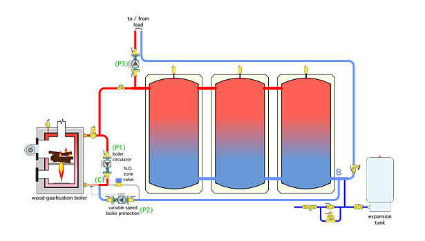
Figure 3 shows the tank array connected to a wood gasification boiler.
The circulator (P2) is a variable-speed “setpoint” unit. It monitors the temperature of the water entering the wood gasification boiler and adjusts its speed to keep the temperature at about 130° F or higher whenever possible. This helps prevent sustained flue gas condensation within the boiler. In effect, the circulator (P2) acts as a “thermal clutch” between the boiler and the tank array or the heating load.
When the circulator (P2) is off there is no flow from the boiler loop to either the tanks or the load. A spring-loaded check valve in the discharge volute of the circulator (P2) prevents thermosiphoning between the tanks and boiler when the latter is off. If otherwise allowed to occur, thermosiphoning would use the boiler as a heat dump. Heat would be lost through the boiler’s jacket as well as up the flue. There is no point in allowing heated water to circulate, albeit at a low-flow velocity, through an unfired boiler.
Potentially cool water returning from the storage tank array, or the distribution system, mixes with heated water from the boiler at point C. The circulator (P1) operates whenever the wood gasification boiler is operating.
The normally open zone valve seen above the circulator (P2) opens during a power failure. This provides an uninhibited low flow-resistance path between the boiler and tank array. When a power failure occurs, residual heat from the boiler is carried into the tank array by thermosiphoning.
Mix it up
The best performing biomass boiler systems are those connected to low temperature hydronic distribution subsystems. That’s because the latter allows for deep discharging of the thermal storage tank. For example, following a boiler burn cycle, the average storage tank temperature may be in the range of 180°. If the system includes a low temperature radiant panel distribution subsystem, the tank array may be able to provide heat to the load at temperatures down to less than 100°. This wide temperature range reduces the number of boiler firings needed, especially during partial load conditions. Fewer but longer firing cycles mean higher overall efficiency and reduced emissions.
When low temperature heat emitters are used, there must be a mixing device between the boiler/storage tank array and the supply side of the distribution system. This is where the circulator (P3) comes in. It can be operated at variable speeds to regulate the mixed water temperature supplied to the load. This is not a new revelation. It’s just a new application for variable-speed injection mixing, a technique that has been used in the hydronics industry for a couple decades. Figure 4 shows the piping and controller details.
The speed of the circulator (P3) varies in response to the water temperature supplied to the distribution system, as measured at sensor S1. This could be a fixed supply temperature or it could be based on outdoor reset control. The latter is preferred because it allows the distribution to operate at the lowest water temperature that can still satisfy the space heat load. The lower the supply water temperature required, the more heat that can be extracted from thermal storage.
In residential and light commercial applications this control functionality is available in relatively inexpensive off-the-shelf controllers. In larger applications, the control logic could be created within a building automation system and used to operate a larger circulator controlled through a variable-frequency drive.
The closely spaced tees that tie the injection riser piping into the distribution system hydraulically separate the circulator (P3) from the main distribution circulator. This is critically important to achieve stable variable-speed injection mixing.
A modulating/condensing auxiliary boiler also has been added in Figure 4. It can operate whenever the wood gasification or storage system cannot maintain the necessary supply water temperature to the distribution system. This boiler’s heat output would be modulated in response to the supply water temperature measured at the sensor (S6). Currently, most available mod/con boilers have the necessary control logic to provide outdoor reset control of this supply water temperature.
Frosting on the cake
There’s one more synergistic detail to include in this system. It’s been added in Figure 5.
A simple differential temperature controller, such as used in solar thermal systems, monitors the difference between the water temperature returning from the distribution system and the heated water available at the tank header (point A). The injection mixing controller controlling the speed of circulator (P3) is allowed to operate when the temperature at the sensor (S3) is at least 5° higher than the temperature of water returning from the distribution system, as measured by the sensor (S4). The injection mixing controller is disabled if the temperature at the sensor (S3) drops to within 3° above the temperature at the sensor (S4).
This control logic scavenges heat from storage to the lowest possible temperature that is still useful to the heating distribution system. It also prevents the injection mixing system from operating when this condition is not met – such as when the wood gasification boiler is not being fired and the storage tank is depleted of useful energy. If the injection mixing assembly were not turned off under this condition, the thermal storage tanks would be maintained at some elevated temperature using heat supplied from the auxiliary boiler. There is not necessary or desirable. The differential temperature control logic also is available in several low-cost off-the-shelf controllers or it could be programmed into a building automation system.
That’s it: A simple, elegant, and easily scalable system that combines a wood gasification boiler, auxiliary boiler, thermal storage, a low temperature distribution system and off-the-shelf controls. This approach also could be used in systems with pellet-fired boilers and wood-chip-fired boilers.
Most of the hardware and control concepts discussed are not specific to wood-fired boilers. Instead, they are readily available devices and proven concepts that have been used in many other modern hydronic systems for quite some time.
Who says you can’t teach those old (hydronic) dogs some new tricks.
This article was originally titled “A complementary relationship” in the March 2015 print edition of pme.
HELPFUL LINKS:


