


Many systems with renewable energy heat sources also have large thermal storage tanks. Examples include systems using biomass boilers and solar-thermal collectors.
I call these heat sources “wild” because they can operate over a wide range of conditions and often at temperatures significantly higher than required by a modern low-temperature hydronic distribution system. Their operation also is not necessarily coordinated with a demand for heat from the loads served by the system.
That word “wild” might seem a bit over-dramatized, but I use it to emphasize that managing these heat sources within a system is very different from turning a gas-fired boiler or some other conventional heat source on and off.
Significant thermal storage also is needed in systems with electric boilers operating on off-peak rates or combined heat and power systems. These applications also produce relatively high water temperatures that mandate one or more mixing assemblies be used between the thermal storage tank and any low-temperature hydronic distribution system.
When storage volume requirements reach a few hundred gallons, some designers look to unpressurized thermal storage tanks as being less expensive on a dollar-per-gallon basis and easier to install compared to pressure-rated steel tanks.
Most unpressurized thermal storage tanks ship in “knock-down” configuration. Individual components are delivered in sizes that can easily pass through a standard passage door. These components are then assembled into a tank with dimensions much larger than that door. This often is the only practical way to fit several hundred gallons of thermal storage into existing mechanical rooms or other interior spaces.
Open to problems
In limited applications it’s possible to route water from unpressurized thermal storage tanks directly to a heat source or hydronic distribution system. However, doing so creates an “open” (vs. closed) hydronic system. Open hydronic systems require specific components, careful design and details not common in closed-loop systems.
One requirement is all wetted components must be resistant to oxidation. Since the unpressurized thermal storage tank is vented to the atmosphere, the water has a “connection” to a virtually unlimited supply of oxygen. It will absorb and release oxygen molecules as it changes temperature. Some of those oxygen molecules will be carried throughout the system and oxygen combined with iron does not lead to good results.
To avoid inevitable corrosion, all wetted surfaces in open systems must be nonferrous. This usually implies the use of materials such as copper, copper alloys (brass and bronze), stainless steel or polymers such as PEX. Ferrous metals such as carbon steel or cast iron should not be used in any open system.
That last sentence precludes direct flow between any wood gasification or pellet boiler with a carbon steel heat exchanger, which is by far the most common type of biomass boiler construction. It also should preclude use of any cast iron circulators. This restriction is clearly documented by circulator manufacturers, but not always complied with since cast iron circulators are far less expensive than those made of bronze or stainless steel. Open systems also preclude the use of standard steel expansion tanks or steel panel radiators.
The restrictions associated with open system design typically require the use of a heat exchanger between the water in the unpressurized thermal storage tank and closed-loop circuits that add or remove heat from the tank.
One of the most common heat exchangers used in large unpressurized thermal storage tanks is a helical coil mode of copper or corrugated stainless steel.
In some systems, one heat exchanger coil is used to dissipate heat from the heat source into the tank’s water. Another coil is used to extract heat from the tank and send it to the load. The connections to the coils typically are routed through the tank walls just above the maximum water line. This reduces the potential for leakage through the tank penetrations.
Opposing directions
To attain maximum heat transfer from a heat exchanger, it’s important that the fluids exchanging heat flow in opposite directions. This is called “counterflow” heat exchange. It produces the highest log mean temperature difference (LMTD) between the two fluids. The higher the LMTD, the higher the rate of heat transfer for a given set of operating temperatures and flow rates.
Figure 1 shows how counterflow heat exchange is achieved when two coils, one for heat input and the other for heat extraction, are used in a thermal storage tank.
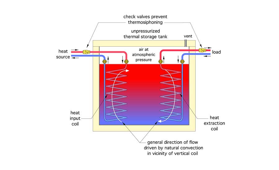
The coil on the left is dissipating heat produced by the heat source into the tank. Hot water enters the top of the coil and passes downward. This is opposite the flow direction of the tank water, which is rising as it absorbs heat and becomes less dense.
The coil on the right is extracting heat from the tank. Cooler water returning from the distribution system is sent to the bottom of the coil and flows upward. This is opposite the downward direction of tank water movement due to increasing density.
Although this two-coil approach has been common for decades, it does not use the available heat exchanger area as effectively as possible. For example, there are several hours in any day when there is no heat input to the tank from solar thermal collectors and likely not from a cordwood gasification boiler that is being properly operated. The heat input coil is idle during such times.
One potential modification to the standard two-coil approach is to combine all coil surface area into a single heat exchanger assembly that can add heat to the tank when the output of the heat source exceeds the load or release heat to the load when the load exceeds the rate of heat input from the heat source.
While this makes sense from the standpoint of utilizing all available coil surface area, it complicates flow management if counterflow heat exchange is to remain in effect in all operating modes.
One solution is to change the flow direction depending on the operating mode of the coil: Top-to-bottom flow when adding heat to the tank and bottom-to-top flow when extracting heat from the tank.
There are several ways to reverse flow through the overall coil heat exchanger. One approach is shown in Figure 2.
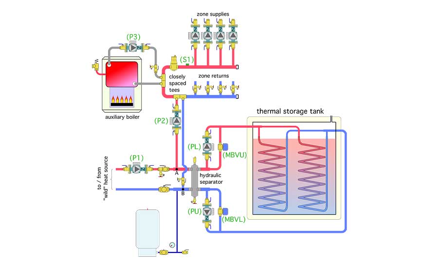
This arrangement uses two circulators (PU and PL) that have mutually exclusive operation. It also uses two motorized valves with high Cv values and 120 VAC spring return actuators to bypass flow around these circulators when they are off.
Circulator (PU) operates to extract heat from the thermal storage tank. It creates flow through the coils from bottom to top. This flow then passes through motorized ball valve (MBVU) to bypass circulator (PL) and continues into the upper right connection of the hydraulic separator. The water can then pass through the separator to point “A” where it can be routed to the distribution system by circulator (P2).
Circulator (PL) operates to add heat to the thermal storage tank. It creates flow from top to bottom through the tank coils. This flow then passes through motorized ball valve (MBVL) and into the lower right connection of the hydraulic separator. From there it can pass through point “B” and back to the “wild” heat source.
The hydraulic separator and the short/generously sized headers connected to it ensure circulators (P1, P2, PL and PU) do not interfere with each other while operating. An electrical schematic that could be used with this system is shown in Figure 3.
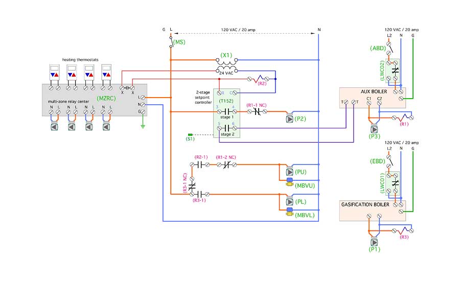
This system uses a two-stage temperature setpoint controller to determine if sufficient heat can be supplied from thermal storage. If it cannot, Stage 2 brings on the auxiliary boiler. The operating logic to coordinate the circulators and motorized ball valves is created by combining the two-stage setpoint controller with three standard relays (R1, R2 and R3).
The following description of operation explains how these devices orchestrate system operation. For the sake of this description, the “wild” heat source is assumed to be a manually fired cordwood gasification boiler that could be fired at any time of the day or night.
Power supply: The gasification boiler and its delivery circulator (P1) are powered by a dedicated 120 VAC/20 amp circuit. The auxiliary boiler is powered by a separate dedicated 120 VAC circuit. The control system and multi-zone relay center (MZRC) are powered by another dedicated 120 VAC circuit. The master switch (MS) must be closed to provide 120 VAC to the multi-zone relay center (MZRC) and to provide 24 VAC through transformer (X1).
Space heating: Upon a call for space heating from any zone thermostat connected to the multi-zone relay center (MZRC), the associated zone circulator turns on and the isolated contacts (X X) close. 24VAC from transformer (X1) passes through the (X X) contacts and turns on the two-stage setpoint controller (T152) and relay coil (R2). The (T152) monitors the temperature at sensor (S1) on the header supplying the zone circulators.
If the temperature at sensor (S1) is ≤ 160° F the Stage 1 contacts in the (T152) close. This passes line voltage through normally closed relay contact (R1-1 NC), turning on circulator (P2). If circulator (P1) on the gasification boiler is off, the “unload” circulator (PU), and motorized ball valve (MBVU) also are turned on by 120 VAC passing through relay contacts (R3-1 NC) (R2-1) and (R1-2 NC).
Heated water flows upward through the tank coils, through valve (MBVU) and into the upper right connection on the hydraulic separator. Circulator (P2) pulls this heated fluid through the hydraulic separator and delivers it to the closely spaced tees in the distribution system. It can then pass into any active zone circuit.
If circulator (P1) on the gasification boiler is on, circulator (PU) and (MBVU) are turned off when contact (R3-1 NC) opens. Circulator (PL) and motorized ball valve (MBVL) are turned on by contact (R3-1). Hot water from the gasification boiler passes point (A) where some of it can be drawn off to the load by circulator (P2). The remainder of the flow passes into the hydraulic separator and downward through the coils in the thermal storage tank.
When the Stage 1 contact in the (T152) closes, a three-minute (adjustable) time delay starts. If this time delay expires AND the temperature at sensor (S1) is ≤ 152° the Stage 2 contacts in the (T152) close. The Stage 1 contacts in the (T152) remain closed. The Stage 2 contacts complete a circuit across the (T T) terminals in the high-limit controller of the auxiliary boiler, turning it on. Circulator (P3) is turned on by the auxiliary boiler. Relay coil (R1) is powered on in parallel with circulator (P3).
Relay contact (R1-1 NC) opens, turning off circulator (P2). Relay contact (R1-2 NC) opens, turning off circulator (PU) and valve (MBVU). All heat to the system now is coming from the auxiliary boiler. This mode continues until the temperature at sensor (S1) reaches 170° or all zones stop calling for heat. If the gasification boiler circulator (P1) turns on, contact (R3-1) closes, and circulator (PL) and zone valve (MBVL) are turned on. Heated water now can pass through the hydraulic separator and into the tank coils, flowing from top to bottom.
If circulator (P1) is on, relay coil (R3) also is energized. Relay contact (R3-1) closes, turning on circulator (PL) and zone valve (MBVL). Relay contacts (R3-1 NC) and (R3-2 NC) open to ensure circulator (PU) and valve (MBVU) are off regardless of any demand for heat. Heated water from the gasification boiler enters the hydraulic separator, passes through and downward through the coils in the thermal storage tank. Return flow from the coils passes through valve (MBVU) and into the lower portion of the hydraulic separator. It then flows back to the gasification boiler.
Further refinements
There are undoubtedly other approaches for creating flow reversal through heat transfer coils to ensure counterflow heat exchange. There are additional details that could be added to the system described above. One would be making circulator (P2) into a variable-speed injection pump that could monitor the supply water temperature to the distribution system and adjust it based on outdoor reset control. Another possibility would be adding an anti-condensation mixing valve between the auxiliary boiler and distribution system if the latter needs to operate at low-water temperatures that would otherwise cause sustained flue gas condensation in the boiler.
Creative hydronic system designers can incorporate these details as deemed necessary. When doing so, be sure to create good documentation so the unique system design is understandable and thus serviceable for many years to come.
This article was originally titled “Flow face off” in the May 2017 print edition of PM Engineer.

