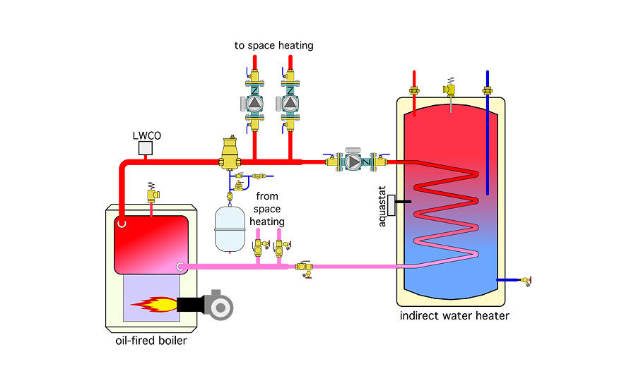


Many pellet boilers are retrofitted into homes with existing hydronic heating. Figure 1 shows a common configuration for these existing systems.
An oil-fired cast-iron boiler supplies several zones of fin-tube baseboard and an indirect water heater. The boiler has a fixed high-limit controller that’s typically set in the range of 170° to 180º F. The relatively low thermal mass and high water temperature requirements of the fin-tube baseboard allow the boiler to remain above the dew point of the flue gases the vast majority of its operating time. Domestic water heating is treated using an indirect water heater controlled as a priority load.
Given this system as the “base,” modifications will be made to achieve the following objectives:
-
Add a pellet-fired boiler with associated thermal storage and optimize its performance by maximizing the duration of on-cycles and off-cycles.
-
Provide heat for domestic hot water from pellet whenever possible, but allow for a high rate of domestic hot water production when needed.
-
Optimize the comfort provided by the fin-tube baseboard under all load conditions.
-
Provide conditions to help sterilize the DHW tank against Legionella growth.
The details that follow achieve these objectives while respecting, as well as sometimes even enhancing the operating characteristics of the hardware involved.
Keep it burning
Pellet boilers are designed to have long “on” cycles. In some systems the pellet boiler can remain on for several hours. These long burns allow the boiler to operate at or close to steady-state combustion conditions over the majority of the cycle. This leads to high thermal efficiency and reduced particulate emissions.
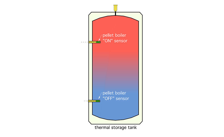
The length of the pellet boiler on-cycle can be increased by making the temperature cycling range of the thermal storage tank as wide as possible.
In a heating-only application, the lower end of the thermal storage temperature cycling range is limited by the ability of the space-heating distribution system to deliver adequate heat to the building. This temperature can be predicted based on outdoor reset control.
An outdoor reset controller continually measures outdoor temperature. Using this temperature and its settings, the controller constantly calculates the current “target” supply water temperature for the distribution system. This is the lowest supply water temperature at which the building’s distribution system and heat emitters can meet the building’s current heating load.
The target temperature calculated by the outdoor reset controller continually is compared to the measured temperature at a sensor located in the upper portion of the thermal storage tank (see Figure 2).
When the temperature at the upper sensor drops a few degrees (e.g., 1/2 of the user set differential) below the calculated target temperature, the outdoor reset controller closes it contacts, turning on the pellet boiler.
Figure 3shows a typical outdoor reset schedule for a fin-tube baseboard system that requires a supply water temperature of 170º when the outdoor temperature is 0º.
The lower the target temperature, the longer the thermal storage tank can supply the load. This lengthens the off-cycle of the pellet boiler and thus lengthens the next on-cycle.
The “off” condition for the pellet boiler is based on achieving a fixed temperature at the lower sensor in the thermal storage tank. This temperature should be relatively high, but must remain below a value at which the pellet boiler would shut itself off based on any safety controls. A common upper limit would be a temperature of 175º in the lower portion of the thermal storage tank.
For smooth-space heat delivery, a mixing device should be installed between the thermal storage tank and the distribution system. It could be a three-way motorized mixing valve or a variable-speed injection pump. Ideally, this mixing device should also operate based on outdoor reset control, allowing smooth heat delivery rather than “bursts” of heat output due to high water temperatures being supplied to the heat emitters.
Boiler protection
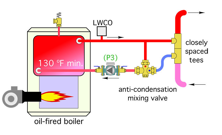
Because outdoor reset control will be used in the modified distribution system, the water temperature returning from the distribution system will, under low partial-load conditions, be low enough to create sustained flue-gas condensation in the existing oil-fired boiler. This can be avoided by modifying the near-boiler piping as shown in Figure 4.
The thermostatic mixing valve modulates to keep the water temperature entering the existing conventional boiler at or above 130º whenever possible. This minimizes flue-gas condensation and allows the distribution system to operate at very low temperatures under partial-load conditions.
Be sure the flow capacity of the thermostatic valve can handle the nominal boiler flow rate while operating at a relatively small 1 or 2 psi pressure drop. Couple the modified boiler piping to the existing distribution system using a pair of closely spaced tees.
DHW complications
Although a “deep” reset of supply water temperature works fine for space heating, it falls short for domestic water heating.
Assuming a domestic hot water delivery temperature of 120º is required at all times, there will be times when the water temperature in the thermal storage tank cannot meet this requirement, especially when that heat has to be pushed through a heat exchanger.
Furthermore, many North American indirect water heaters have internal coils sized for relatively high water temperatures such as 180º during the domestic water-heating cycle. Thus, if water to the indirect coil is supplied from the thermal storage tank there will be times when even 140° or 150º might not produce the required heat transfer across the coil in the indirect water heater.
This presents a quandary. Should the designer:
A. Only allow the thermal storage tank to drop to perhaps 160º so that a reasonable rate of domestic hot water production is always possible?
B. Completely separate the domestic water heating from the pellet boiler portion of the system and use fossil fuel for all DHW needs?
C. Tell the clients to “adapt” to the possibilities of limited domestic hot water production, at times, when the thermal storage tank has dropped to a relatively low temperature?
Option A essentially defeats the purpose of using outdoor reset control to initiate pellet boiler operation. It significantly limits the temperature cycling range of the thermal storage tank to conditions that are only present during design load conditions. It’s not a good solution.
Option B uses fossil fuel rather than pellets to meet the domestic water-heating load. In some situations where there is limited DHW use, this may be tolerable. However, if the client’s objective is to use pellets to displace fossil fuel whenever possible, this is a big compromise, especially if there’s a significant DHW load.
Option C. If you’ve been in the heating business a few years you know this is a “nonstarter” for most clients. They don’t want to hear about an expensive heating system that can only supply domestic hot water on “its” terms rather than when they want it.
New trick
This is where a unique control solution comes in. It uses a differential temperature controller — the same as used in solar DHW systems — to transfer available energy from the thermal storage tank to the heat exchanger within an indirect water heater. This subsystem is shown in Figure 5.
This subsystem operates independently of the controls that can add heat to the indirect water heater from the oil-fired boiler.
The operating logic for the differential temperature controller is as follows:
IF (S6) ≥ (S7) +10º THEN circulator (P7) is ON
IF (S6) ≤ (S7) + 5º THEN circulator (P7) is OFF
The on-differential of 10º and the off-differential of 5º are only suggested values. They can be adjusted on most differential temperature controllers.
Given the operating logic for the pellet boiler, this heat transfer should occur during each of its firing cycles.
Considering that the upper portion of the thermal storage tank will reach high temperatures in the range of 180° to 195º as the pellet boiler firing cycles near completion, the indirect water heater should reach temperatures high enough to fully sterilize the water of legionella bacteria during each pellet boiler firing cycle.
An anti-scald thermostatic mixing valve on the outlet of the indirect water heater is an absolute must to ensure safe DHW delivery temperature (≤ 120º). Some differential temperature controllers also can be set to limit the temperature to which the indirect tank is heated and override the Delta-T based control logic.
If the pellet boiler is turned off, as it might be during summer, there will be no heat transfer from thermal storage to the indirect water heater. However, if the aquastat (AQ1) mounted to the indirect water heater, and set relatively low at 120º, calls for heating, it will turn on two circulators and the oil-fired boiler to ensure that domestic hot water remains available as a priority load.
The big picture
Figure 6shows a schematic of the entire system, including several of the details previously discussed.
The piping between the pellet boiler and thermal storage tank allows for anti-condensation protection of that boiler, and prevents thermosiphoning between the thermal storage tank and pellet boiler when the latter is off.
A variable-speed injection circulator is set up as the mixing device between the thermal storage tank and the distribution system. The controller regulating this circulator monitors outdoor temperature and the supply water temperature to the distribution system. It uses outdoor reset control logic to control the injection flow so the necessary water temperature is supplied to the distribution system.
Temperature sensors (S6) and (S7) allow for the differential temperature-based transfer of heat from thermal storage to the indirect tank as previous described.
In the next column we’ll look at a control system that can manage the complete system.
This article was originally titled “Whenever it is available” in the August 2016 print edition of PM Engineer.


