
Most of the pellet boilers being installed in North America are retrofit into existing hydronic heating systems that have one or more fossil-fuel boilers.
This scenario can be useful. The pellet boiler can serve as the “base load” heat source, often supplying more than 90% of the seasonal heating energy required. The existing boiler or boilers are retained to meet peak load or to provide all heat input to the building if the pellet boiler is offline for maintenance or service issues.
With this concept in mind, many engineers view the combined heat sources as a routine “lead/lag” system. The pellet boiler would operate as the fixed Stage 1 boiler. A single existing boiler would operate as Stage 2. If the system has more than one existing boiler, they would operate as stages 3, 4, etc.
This approach always favors heat input by the pellet boiler, but automatically brings the other boilers online as necessary to ensure an adequate supply temperature to the system. If there are multiple existing boilers, and they are identical, the control system can be configured to rotate the firing order of those boilers to provide approximately equal run time.
Dealing with thermal storage
Although the essence of a multiple boiler control approach does apply, there are distinct differences relative to systems using multiple/identical boilers.
Most pellet boiler systems require water-based thermal storage to achieve long burn cycles followed by long off cycles. Long on/off cycles allow the boiler to achieve high thermal efficiency and low emissions. Conversely, systems without thermal storage often fall short of achieving their potential thermal and emissions performance.
Storage is especially important for pellet boilers serving distribution systems with several zones of low thermal mass heat emitters, although there are no universally accepted standards for sizing a thermal energy storage tank for a pellet boiler. However, guidelines from various sources suggest tank volumes in the range of 1 to 2.5 gallons of water per 1,000 Btu/hr., of rated pellet boiler capacity.
Think of the thermal storage tank as a “heat battery” and the pellet boiler as the “battery charger.” The objective is to discharge the heat battery to the greatest extent possible while still providing adequate supply water temperature to the distribution system. Once the tank is fully discharged, the pellet boiler is turned on, and kept on, to fully charge the tank to a relatively high temperature, often in the range of 170° to 180º F.
This control action is accomplished by turning on the pellet boiler when a temperature sensor in the upper portion of the thermal storage tank drops below some limiting value. The pellet boiler remains on until a temperature sensor in the lower portion of the tank reaches some high limiting value. The “on” and “off” temperatures for the pellet boiler can be set values or determined based on implied heating load (e.g., based on outdoor reset).
Some pellet boilers have internal controllers that handle these functions, while others rely on external controllers. Furthermore, this control action usually takes place independently of any demand for heat by the distribution system. The latter is an important difference between how boilers in most hydronic systems are fired (e.g., only when there is a demand for heat from a load) and how a pellet boiler typically is operated. This difference must be reflected in how a multiple boiler system involving a pellet boiler is controlled.
Tank circulator equals Stage 1
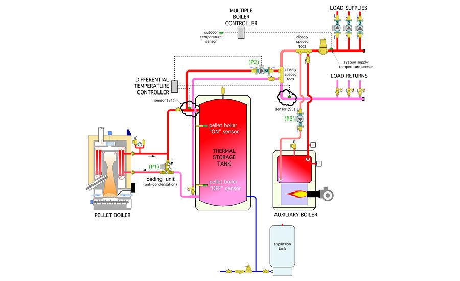
The best way to integrate a multiple boiler controller into a system that includes a pellet boiler and associated thermal storage is to think of the storage tank and not the pellet boiler as the fixed lead heat source. Instead of turning on a burner, the Stage 1 contacts of a multiple boiler controller turn on a circulator that moves heated water from the thermal storage tank to the distribution system, as shown in Figure 1.
Circulator (P2) can be either a fixed-speed circulator or a variable-speed “injection” circulator. The latter allows the water temperature in the distribution system to be adjusted based on outdoor reset control. As the outdoor air temperature decreases, the supply water temperature to the distribution system increases.
If the water supplied from the thermal storage tank to the distribution system is unable to achieve the required target supply water temperature within a short period of time, the second stage contacts of the two-stage boiler controller close. This turns on the auxiliary boiler and its associated circulator. At this point, flow from both the thermal storage tank and the auxiliary boiler is directed into the distribution system. This is fine unless the return water temperature from the distribution system begins to approach the temperature in the upper portion of the thermal storage tank. Such a condition means the thermal storage tank can no longer provide any useful heat to the distribution system.
If the return water temperature from the distribution system climbs above the temperature in the upper portion of the thermal storage tank, and circulator (P2) remains on, heat produced by the auxiliary boiler would be added to the thermal storage tank. That situation should be prevented with one possible exception that will be discussed in my January 2017 column.
Delta-T to the rescue
A simple way to prevent heat generated by the auxiliary boiler from “back-feeding” thermal storage is to compare the temperature on the return side of the distribution system to the temperature in the upper portion of the thermal storage tank. As long as the return temperature is lower than the tank temperature, the tank can remain “online” with the distribution system and contribute some heat to the load.
A simple differential temperature controller, such as that used in many solar thermal systems, can be used for this purpose. The two temperature sensors for this controller would be installed as shown in Figure 2.
Sensor (S1) measures the temperature at the upper tank header. This is the temperature of supply water available from either the thermal storage tank or the pellet boiler if the latter happens to be operating. Sensor (S2) measures the temperature on the return side of the distribution system.
The operating logic for the differential temperature controller, based on sensors (S1) and (S2), is as follows:
IF (S1) ≥ (S2) + 5º F THEN circulator (P2) is on when Stage 1 heat input is called
IF (S1) ≤ (S2) + 2º F THEN circulator (P2) is disabled when Stage 1 heat input is active
In either case, Stage 2 of the multiple boiler controller will turn on the auxiliary boiler and its associated circulator (P3) if the temperature at the supply side of the distribution system does not approach the target temperature determined by the multiple boiler controller within a short time.
The 5º and 2º offsets given above are adjustable on most differential temperature controllers. The 2º offset is the smallest practical differential that can be reliably verified by the controller given the tolerance of the thermistor sensors involved. Measuring temperature differential this small also requires sensors that are identical and mounted in an identical manner. For example, don’t mount one sensor on the surface of a copper pipe and the other on the surface of a steel pipe. If in doubt, mount both sensors in identical insertion wells.
In larger systems, the differential temperature control logic could be programmed into a building automation system.
If the auxiliary boiler is oversized for the design load, and the distribution system is highly zoned, allowing the auxiliary boiler to partially heat the upper portion of thermal storage can provide a buffering effect for a boiler that is not properly sized for the load. It can remedy an existing short cycling issue. We’ll discuss the specifics of how to do this in next month’s column.
This article was originally titled “Staging without back-feeding” in the December 2016 print edition of PM Engineer.


