


In my August pme column we discussed a strategy for adding a pellet-fired boiler to a typical North American hydronic heating system with a conventional boiler, multiple heating zones of fin-tube baseboard and an indirect water heater.
That strategy was based on several objectives.
-
Allow good cycling and emissions performance of the pellet-fired boiler through use of thermal storage and “temperature stacking” control logic.
-
Provide heat for domestic hot water from pellets whenever possible, but allow for a high rate of domestic hot water production when needed. Also, allow the existing boiler to heat domestic water if the pellet boiler is turned off.
-
Optimize the comfort provided by the fin-tube baseboard under all load conditions.
-
Provide conditions to help sterilize the DHW tank against Legionella growth.
The necessary piping details were developed and assembled into the system shown in Figure 1.
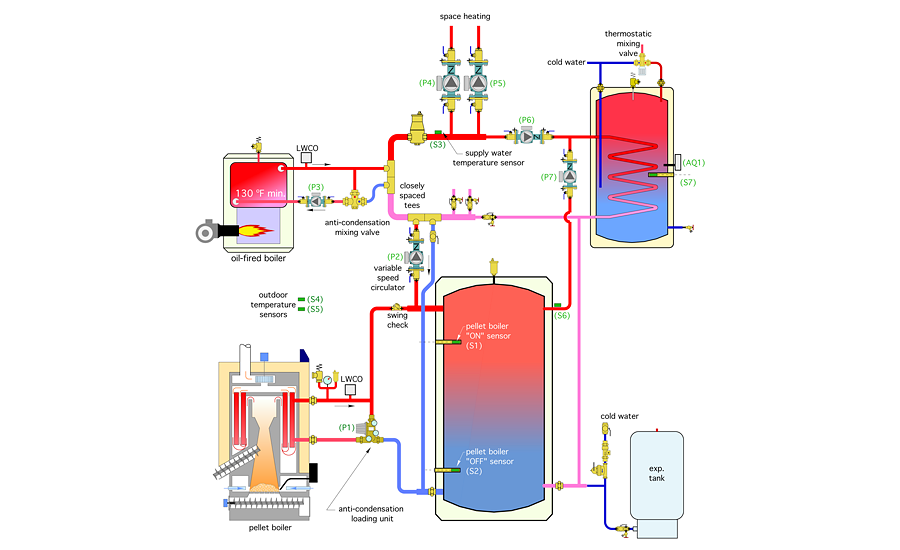
This system is assumed to have two independently controlled space heating zones, but could easily be expanded to more by adding zone circulators in parallel with and adjacent to circulators (P4) and (P5).
Options
What remains is to assemble a control system that can orchestrate all the required subsystems and ensure the design objective embodied in the piping design is realized.
One approach would be to search for a single box “plug and play” controller from an established manufacturer that could receive information from all seven temperature sensors — and multiple switch contacts — in the system. The controller then processes this information into outputs to operate the circulators and heat sources to achieve the design objectives.
Unfortunately, that single box solution doesn’t exist due to the customized nature of this system combined with limited (at least at present) usage of pellet-fired boilers in North America.
Another option is to use a programmable building automation system that could accept the digital and analog inputs and process them into the required outputs based on programming instructions. Although I’m sure a number of available BAS products could be configured to operate this system, the cost and complexity of such controls typically precludes their use in residential or light commercial applications.
Still, don’t give up on the concept of highly programmable controllers for smaller system applications. Relatively inexpensive microcontrollers such as the $50 Raspberry Pi 3 that are increasingly used for computer fundamentals training and “hobby” applications have more than enough computational power to handle any residential or light commercial HVAC application.
What they need is a standardized way to interface to the temperature, pressure and flow inputs associated with HVAC applications, and output interfacing to drive line voltage devices drawing several amps of current. Watch for these inexpensive yet powerful microcontrollers to emerge as the “brains” of future HVAC control systems.
Tried and true
Currently, I’ll present a control system built around readily available controllers. Individually these controllers provide single control actions such as outdoor reset control, temperature setpoint control, variable-speed injection mixing and differential temperature control. Collectively they can provide all the functions necessary for precise control of the hardware shown in Figure 1.
One advantage of this approach is all the controllers I’ve selected have been available for several years and from multiple suppliers. If one of these controllers fails, odds are it can be replaced with either:
-
An identical controller from the same manufacturer;
-
A newer version of the controller with the same control actions; or
-
A controller from a different manufacturer but with the same (or very similar) basic functionality.
This interchangeably helps ensure the control system can be serviced, if necessary, many years after it is installed and without major modification of the hardware being controlled.
The tradeoff with this approach is it depends more on “hard-wired logic” (e.g., the proper interconnection of the various controllers), rather than software that maps inputs to outputs, as would be the case with a BAS or microcontrollers. Hard-wired logic is a bit more time consuming to install and requires good physical organization of the hardware, preferably within a control cabinet.
I recommend most of the wiring between controllers be done in the shop rather than in the field. The wiring that eventually connects to controlled devices such as circulators, boilers or motorized valves should be run to labeled terminal strips within the cabinet. Once the cabinet is installed, wiring to these devices can easily be routed to the labelled terminals without concern that the proper hard-wired logic is being created in the process.
The control system for the system in Figure 1 is represented as a ladder diagram in Figure 2.

The light green boxes represent specific controllers from tekmar. The light orange boxes show which terminals within the oil-fired boiler and pellet-fired boiler are connected to the control system. The gray box is a multi-zone relay center, a commonly used controller for zoned hydronic systems. Also shown are relay coils, relay contacts and temperature sensors.
Most (but not all) the controllers and relay coils operate on 24 VAC power, which is provided by the secondary winding of the transformer seen at the top of the ladder.
Note that all the controllers, controlled devices, sensors, switches and other hardware are named or labelled with abbreviations. It is imperative the designated name (or abbreviation) of a given component be consistent between the piping schematic and wiring diagram.
Spell it out
No control wiring diagram is complete without a carefully worded description of operation. It should describe exactly what happens, starting with a call for heat and ending when the call for heat is no longer present. It should make frequent references to the assigned names (or abbreviations) of the hardware in the wiring and piping schematics. The description of operation also can be broken up into multiple sections, one for each operating mode or subsystem.
The following is a description of operation of the system shown in Figures 1 and 2. I recommend you put a copy of the piping schematic (Figure 1) and the wiring schematic (Figure 2) in front of you as you read this description. Read a sentence or two and then find the equipment referenced in that text on both diagrams.
Space heating mode
When either of the space-heating zone thermostats call for heat, the associated zone circulator (P4) or (P5) is turned on by the multi-zone relay center (MZRC). The isolated (X X) contacts within the (MZRC) close to supply 24 VAC to the tekmar 356 injection mixing controller (T356). The (T356) measures outdoor temperature using sensor (S4) and calculates the necessary target supply water temperature to be established at sensor (S3). If the measured supply water temperature at sensor (S3) is lower than the calculated target temperature, the speed of circulator (P2) increases to inject heated water from the thermal storage tank, or coming directly from the pellet-fired boiler, into the distribution system at a higher rate (e.g., to increase the rate of heat transfer into the distribution system).
If the (T356) controller reaches 30% pump speed, it closes a set of contacts marked (boil). These contacts pass 24 VAC to an outdoor reset controller (T256-2) which determines if the oil-fired boiler needs to operate based on its settings and the current outdoor temperature. If (T256-2) fires the oil-fired boiler, relay coil (R3) also is energized along with circulator (P3). The normally closed contacts (R3-1) open to turn off the injection circulator (P2). This prevents heat derived from the oil-fired boiler from being inadvertently transferred to the thermal storage tank. The oil boiler will fire until the (T256-2) controller determines the supply water temperature is sufficient to meet the load. When this occurs, the injection pump (P2) will be re-enabled and heat from thermal storage will again attempt to meet the target supply water temperature at sensor (S3). This cycle will repeat, if necessary, if the thermal storage tank is unable to meet the target temperature at sensor (S3).
DHW mode
Whenever the temperature at sensor (S6) is 10º F or more above the temperature at sensor (S7), circulator (P7) is turned on by differential temperature controller (T156). This transfers heat from the thermal storage tank to the indirect water heater. Whenever the temperature at sensor (S6) drops to 4º or less above the temperature at sensor (S67), circulator (P7) is turned off. This mode of operation should allow the indirect water heater to reach relatively high temperatures as the pellet boiler firing cycle nears completion. The injection circulator (P2) is turned off by normally closed relay contact (R1-1) if the oil-fired boiler is operating to heat domestic water.
If the pellet boiler enable switch is opened, the pellet boiler will not operate. The indirect water heater will be heated when the temperature of the water drops below the setting of aquastat (AQ1). This will initiate priority domestic water heating. Any space heating circulators that might be running are temporarily turned off. The oil-fired boiler is enabled along with circulator (P3). The water temperature of the oil-fired boiler is limited by the boiler’s high-limit controller. Circulator (P6) is turned on to move heat from the oil-fired boiler to the coil of the indirect water heater.
Pellet boiler firing
The pellet boiler is fired when the upper tank sensor (S1) drops to a temperature determined by an outdoor reset controller (T256-1). It remains on, regardless of load status, until the lower tank sensor (S2) reaches a limit setting of 175º. This “stacks” the tank with high temperature water at the end of each pellet boiler firing cycle.
Settings
Documentation for the control system also should specify initial settings for all the controllers. In some installations, the initial settings will be changed to fine-tune the system to the particular responses of the system and how it interacts with the heat-loss characteristics of the building. These changes also should be logged along with the date they are made and who made them.
Controllers differ in how settings are entered. For example, some temperature setpoint controllers place the differential between “contacts closed” and “contacts open” below the setpoint, while others center the differential on the setpoint temperature. Both can achieve the same control action, but will require different setting values to do so.
Given the possibility of a change in controllers over the life of the system, it’s also good to show some “generic” control requirements that represent what the goal of the control action is. These can be shown in addition to specific controller settings. Figure 3 shows an example.

This graph shows the target water temperatures for three different controllers represented in Figure 2, specifically the T265-1, T256-2 and T356.
The control actions of all these controllers, in this system, are based on outdoor reset. The (orange) reset line is the target supply water temperature that the injection mixing controllers (T356) is attempting to maintain at sensor (S3) whenever there is a space heating demand. The (blue) reset line is the temperature the (T256-2) controller is attempting to maintain using the existing boiler. It’s 5º lower than the mixing reset line. This favors heat input from the thermal storage tank whenever possible, but also activates the existing boiler if the supply water temperature is “drooping” slightly below the target value. The (red) reset line indicates the water temperature at the upper tank sensor at which the pellet boiler is fired. The pellet boiler is turned off whenever the lower tank sensor reaches a temperature of 175º.
After you’ve designed the piping and controls for an upcoming system, be sure to provide documentation that shows and describes exactly how that system should operate. Print it out and put it in a binder that’s left near the system so that future service personnel can use it. Also, put a copy of the installation instructions for each of the controllers used in that system into that binder.
That documentation could make the difference between a system that provides decades of reliable service vs. an “orphan” that nobody will attempt to diagnose and repair.
This article was originally titled “Orchestration” in the September 2016 print edition of PM Engineer.


