Large garage facilities are among the best applications for hydronic radiant floor heating. The reasons supporting this statement include:
- These facilities have bare concrete floors that enable floor heating circuits to operate at relatively low water temperatures.
- The durability of slab heating is well matched to the heavy traffic floors in such facilities experience.
- All combustion and make-up air can be isolated to a single mechanical room away from combustible fuels, paints, or other chemicals.
- The "barefoot"
Thermo 101
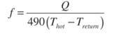
The thermodynamic relationship between distribution flow rate, heat transport rate, and temperature difference between the supply and return piping serving the manifold station is given in Equation one.Equation 1
Where:
Q = rate of heat transfer (Btu/hr)
Thot = temperature of fluid in supply pipe (?F)
Treturn = temperature of fluid in return pipe (?F)
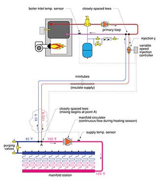
490 = a constant for water (use 479 for 30% glycol, 450 for 50% glycol)Here's an example: Assume a large manifold station is located 250 feet from the mechanical room. At design load, it must supply 250,000 Btu/hr to its circuits at a temperature of 105 deg F. The design temperature drop between the supply and return manifolds is 20 deg F. The boiler system produces water at 175-deg F at design load, and the mixing is done in the mechanical room as shown in Figure 1. What flow rate is needed to the manifold station? What size copper tubing is required for this flow?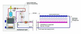
The flow rate to the manifold station is calculated using Equation one:
To maintain flow velocity no higher than four feet per second, a 2" copper tube set is required between the mechanical room and manifold station.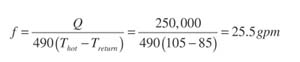
However, if the mixing is done at the manifold station, the supply pipe is now carrying 175 deg F water. The required flow rate between the mechanical room and manifold station is again calculated using Equation one:
A 3/4-inch tube could handle this flow rate with the flow velocity remaining under four feet per second. The large temperature drop between the supply and return injection risers is what enables this relatively low flow rate to deliver such a high rate of heat transfer. A single-zone minitube piping arrangement that allows for mixing at the manifold is shown in Figure 2.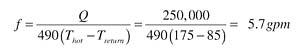 Notice how the relatively short injection risers in Figure 1 have been "stretched out"
Benefits Galore
The "Mix at the Manifold"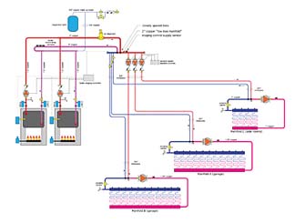
Running the Numbers
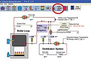
Figure 3 shows the piping schematic for a three-zone minitube distribution system recently installed in a 9,000-square-foot garage building.The dual boiler system supplies 360,000 Btu/hr at design load. Each boiler circulator operates independently, turning on three minutes before the burner fires and remaining on three minutes after the burner turns off. The former uses heat from the system water to warm the boiler's heat exchanger prior to firing, and thus minimize flue gas condensation. The latter purges residual heat from the boiler heat exchanger.
Heated water is delivered to a low loss manifold via a pair of closely spaced tees. The low loss manifold supplies three independently controlled injection pumps, each equipped with internal spring-loaded check valves. At design load, these pumps have a combined flow rate of approximately nine gallons per minute. The relatively low flow rate (for two-inch pipe) and short manifold length reduce head loss along the manifold to almost zero. This, in turn, minimizes interaction between the injection circulators as they operate at various speeds. The low loss manifold detail is also simpler and less expensive than constructing a parallel primary loop to achieve the same hydraulic separation between circulators.
Because the supply and return minitubes connect to the manifold station using closely spaced tees, and because there's very little head loss between them at the low loss manifold, they can be designed as if they formed a "stand-alone"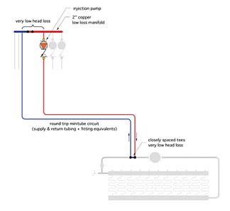 Step 4: Use Equation 2 and the associated data to estimate the head loss of the minitube circuit. Be sure to apply the correction factor if antifreeze is used in the system.
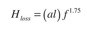
Equation 2
Where:
Hloss = head loss (feet of head)
a =constant from Table 1 based on tube type and size
l = total equivalent length of minitube piping + fittings (feet)For a 30% glycol solution, multiply the calculated head loss by 1.21. For a 50% glycol solution, multiply the calculated head loss by 1.38.
Example: Assume the round-trip minitube circuit length is 600 feet of 3/4-inch PEX-AL-PEX tubing.
The value of (a) for this tubing from Table 1 is 0.00303.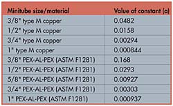
The calculated head loss of this circuit at the design flow rate calculated in Step 2 is:
Step 5: Select a circulator with a curve that passes through or just above the target operating point (in this case, 4.64 gallons per minute flow at 26.7 feet of head (see Figure 5).
Step 6: As always, the designer should investigate the "what if"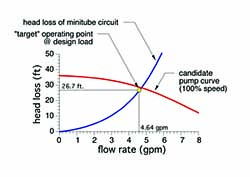
Summary
Minitube systems can save thousands of dollars in initial cost in large garage facilities using radiant floor heating. They are equally applicable in large snowmelting systems.The higher the temperature difference between the supply water temperature and floor circuit return temperature, the greater the heat transport per gpm of minitube flow.
The sizing and selection of a minitube piping set and injection pump use straightforward hydronic design procedures. A prudent designer uses these procedures to investigate various combinations of tube type/size for the resulting injection pump requirement. These results are then compared on the basis of installation and operating cost. The goal is to achieve a low life-cycle cost.
- For additional information on the Injection Mixing Simulator software, visit www.hydronicpros.com.
