It's hard to have a discussion on modern hydronic heating and not talk about primary/secondary (P/S) piping. Listening in on such a conversation, someone new to hydronics might conclude that P/S is one of the latest innovations in hydronics.
Not so. According to the Bell & Gossett Co., P/S piping dates back over 50 years (to 1954). You can read about this in the B&G publication, Primary Secondary Pumping Applications Manual (Bulletin No. THE-775), which I consider one of the classic references on the subject.
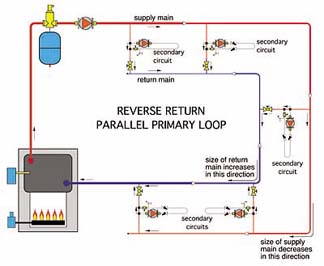
Interestingly, the type of system this manual describes is not the piping configuration most designers of modern hydronic systems picture when the subject of P/S piping comes up. To be specific, the B&G publication describes parallel primary loop systems, whereas the majority of present designers working with residential and commercial applications of P/S piping are accustomed to series primary loops. The difference between these configurations is shown in Figure 1.
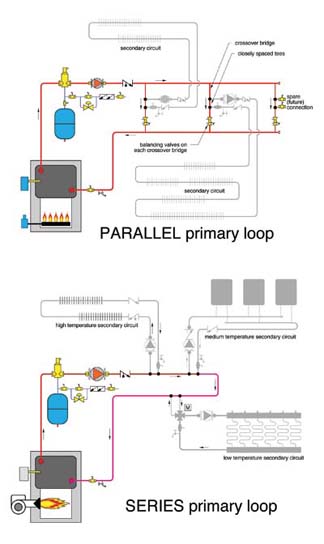
The answer is that a parallel primary loop provides equal supply temperature to each secondary circuit, whereas a series primary loop does not.
Having equal supply temperature to each secondary circuit is very important for chilled water cooling distribution systems. The terminal units in such systems must operate on a fairly narrow temperature rise to provide proper latent cooling (dehumidification).
Maintaining equal supply temperature to each secondary circuit serving a heating load can also be important. Heat emitter sizing is simplified because the sequential temperature drop between successive secondary circuits that occurs in a series primary loop is not present in a parallel primary loop.
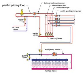
One example of where a parallel primary loop can be useful in a heating application is the multizone minitube system shown in Figure 2.

Divvy It Up
Flow proportioning through the crossover bridges in a parallel primary loop is regulated by how the "mains"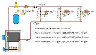
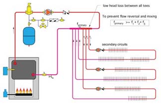
What's more important is ensuring the flow rate through each crossover bridge is equal to or slightly greater than the flow in the secondary circuit it serves. This prevents flow reversal at the closely spaced tees and subsequent mixing at the upstream tee. The latter will lower the supply temperature to the secondary circuit.
Alternate Approaches
The two key benefits of a classic parallel primary loop are:1) Hydraulic separation between simultaneously operating circulators; and
2) Providing the same supply temperature to each secondary circuit.
Other approaches that offer these same benefits include:
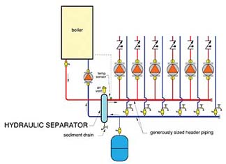
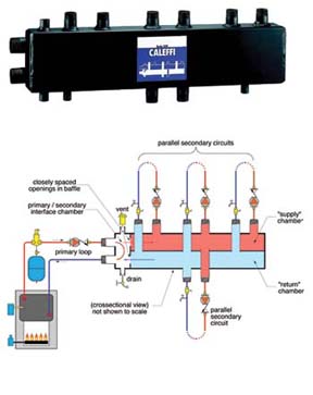
- Hydraulic separators;
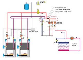
- Low loss manifolds; and
- Pre-assembled P/S manifold systems.
With either of these piping configurations, check valves must be installed downstream of each distribution circulator to prevent flow reversal.
The options listed here are arguably simpler and use less hardware than a classic parallel primary loop. The latter makes most sense when the secondary circuits are spread throughout the building. In such cases, the parallel primary loop should be set up for reverse return flow. An example of such a system is shown in Figure 7.
Notice the baffle with two holes near the left end of this device. This detail provides the hydraulic separation between the "primary chamber"
What About Series Primary Loops?
In systems where there's a significant difference in supply temperature requirements between secondary circuits, a series primary loop is a better choice. An example of the latter is a system using fin tube baseboard on one secondary circuit and low temperature radiant floor heating on another. The higher temperature secondary circuits should always be teed in near the beginning of the primary loop, with the lower temperature secondary circuits connected near the end. This sets the stage for a relatively high temperature drop around the primary loop, which in turn lowers flow requirements and reduces the size and power demand of the primary circulator. Primary loop temperature drops on the order of 30 degrees to 40 degrees F are entirely possible, and even desirable.Figure 9 shows a variation of the series primary loop intended to provide equal supply temperatures to each secondary circuit as well as hydraulic separation. The key to making this arrangement work is low head loss along the common piping. A flow-check or spring-loaded check should be installed in each secondary circuit to prevent flow reversal and heat migration. Also, to prevent flow reversal in the primary loop and subsequent reduction in the secondary supply temperature, be sure the primary loop flow rate is equal to or greater than the total of all secondary flow rates.