
When you operate a fleet of 32 delivery trucks year-round in upstate New York, you have some decisions to make. One is how you would expect to start all those diesel engines when the outside temperature is -15

Small Tubes Delivering Big Performance
The underlying concept in a minitube distribution system is transporting relatively high temperature water from the mechanical room to the location of the manifold stations, and then mix as necessary to supply the floor circuits.This approach takes advantage of the large temperature difference between the water sent to the manifold station(s) and the water returning to the mechanical room.
At design load conditions, a typical minitube distribution system supplies water at 170-200
This flow would require a 2-inch tube set between the mechanical room and manifold station. The difference in installed cost of between these tube sets over a total distance of 1,000 feet or more would be substantial.
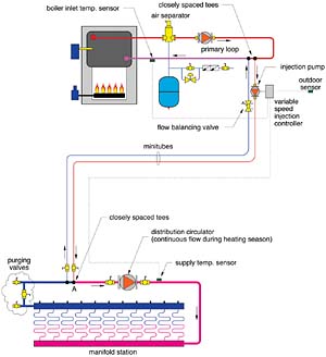
Notice that the minitube piping connects to the parallel primary loop as well as the manifold station piping using a pair of closely spaced tees. This detail eliminates interference between the pressure differential created by the injection pump and those created by the primary loop circulator and manifold station circulator.
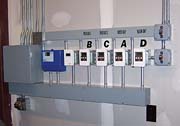
The minitube system at the McCraith garage has four individually controlled manifold stations, each serving a different zone of the building. The basic system schematic is shown in Figure 3 (Editor's Note: See print issue for Fig. 3).
Black Gold
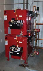
The heat source for the system is a pair of waste oil boilers, each having a rated output of 350,000 Btu/hr (Figure 5). A microprocessor-based staging control operates both the burners and circulators on each boiler. Each boiler circulator operates for a short time before the burner is fired, and continues to run for a few minutes after the burner is turned off to purge residual heat from its associated boiler.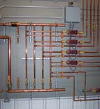
The return minitube from each manifold station returns to the mechanical room and passes through a flow metering balancing valve before connecting back to the crossover pipe. The balancing valve allows the resistance of the minitube circuit to be adjusted so the injection pump runs at full speed under design load conditions. This maximizes the rangeability of the injection system for precise temperature control.
The manifold stations use standard cast brass components. The two large manifold stations have design loads of approximately 260,000 Btu/hr each, and are supplied by 1-inch copper minitubes. Two smaller manifold stations serve a wash bay and maintenance bay at about 90,000 Btu/hr each, and are supplied by 3/4-inch minitubes. All minitubes are insulated between the mechanical room and manifold stations.
Each manifold station has its own distribution circulator. The circulators are automatically turned on when the outdoor temperature drops below 60
The Benefits Continue
Besides saving on material and installation cost, the small minitubes reduce system volume. This, in turn, may reduce the size of the system's expansion tank. It also reduces the volume of antifreeze in systems that require it.Because the distribution circulators only handle the flow and head loss of the manifold stations, and not that of the piping between the manifolds and mechanical room, it may be possible to use smaller circulators.
The small minitubes also reduce piping heat loss between the mechanical room and manifold stations relative to that of larger piping operating at lower temperature drops.
The McCraith garage system has been in operation since February 2004. It was brought online during one of the coldest winters in recent history in upstate New York, and has already proven it can deliver the heat precisely when and where it's needed.
If you design floor heating systems for larger buildings where the manifold stations may be a considerable distance from the mechanical room, a minitube distribution system may be just what you need to reduce cost, improve control and speed installation.
