
So, your firm won the bid to design a new commercial project that includes a hydronic radiant snow- and ice-melting system. How do you start and what do you need to know throughout the design process to ensure you deliver on meeting the client’s expectations for performance, schedule and budget?
There are general concepts every engineer should know when it comes to the design process for an efficient, effective snow- and ice-melting system, including zoning, slab construction, system loads, system design, control strategies and construction documents.
This broad overview will provide guidance for the fundamentals to know when designing a hydronic radiant snow and ice melting system. However, for complete details on system design, be sure to contact a commercial radiant design professional or a radiant piping manufacturer’s design department for expertise beyond the basics.
Why snow- and ice-melting?
Before delving into the design practices, it’s important to understand the “why” behind a hydronic radiant snow- and ice-melting system.
Traditional snow removal methods are time-consuming and costly. Hydronic radiant systems are embedded in or buried under a slab or hardscape and can activate on demand to start melting snow or ice at the first sign of precipitation.
With this solution, building owners and property managers can enjoy ease of maintenance with faster response times as well as cost savings due to the elimination of salting or sanding and the labor that comes along with it. Snow- and ice-melting systems also provide cleaner surfaces and help preserve exterior materials while also offering safer access for reduced liability risk.
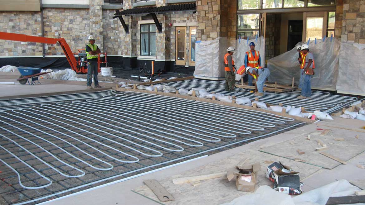
From sidewalks and parking lots to transit platforms, ambulance bays, and helicopter pads, the applications are numerous for snow- and ice-melting systems. All in all, they provide a safe, convenient, cost-effective solution for commercial projects in cold-climate regions that experience snow and ice throughout the winter months.
Hydronic radiant snow and ice melting systems have the same concept as in-slab radiant heating systems, except instead of comfort as the end goal, the main point is to provide adequate heat to melt snow and ice from exterior surfaces.
Design process
Hydronic radiant snow and ice melting systems have the same concept as in-slab radiant heating systems, except instead of comfort as the end goal, the main point is to provide adequate heat to melt snow and ice from exterior surfaces.
That said, the first step in the design process focuses on determining the zones.
Zoning
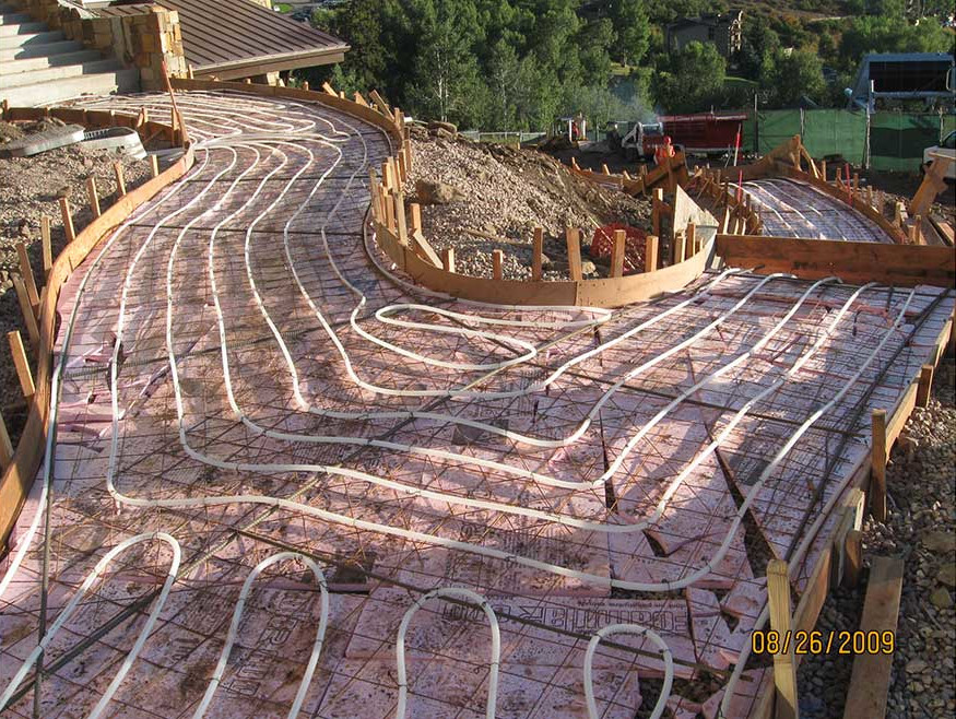
When determining the zones, it’s important to look at the scope and make sure it’s clear where snow- and ice-melting makes sense. It’s important to have a conversation with the building owner to find out which areas are critical for snow- and ice-melting and which areas are not necessarily needed. Ask the question — “Does the entire parking lot or building perimeter require snow- and ice-melting, or are only select areas, such as main walkways and entryways vital?”
Next, you need to look at the actual zoning itself, which is based on the areas of control, scheduling, and slab construction. It’s important to note that the zones do not need to be defined based on manifolds. Know that multiple manifolds can serve one large zone, so it’s not necessary to have one zone for each manifold. What is important is the piping system design and the associated controls for the system.

Zones do not need to be defined based on manifolds. Know that multiple manifolds can serve one large zone, so it’s not necessary to have one zone for each manifold. What is important is the piping system design and the associated controls for the system.
Slab construction
The next step in the design process is the slab construction. It is essential to coordinate with the building architect, structural engineer, civil engineer and landscape architect to ensure all parties are aligned on how the slab will be constructed, where the radiant tubing will be located in the slab, and how the slab may be impacted by the radiant tubing.
It is also important to coordinate with the trades to gain an understanding of the slab thickness as well as the slab properties (e.g., concrete or paver types, etc.). Knowing this information will determine the R-value and the required water temperatures necessary to obtain the target surface temperatures to melt the snow and ice.
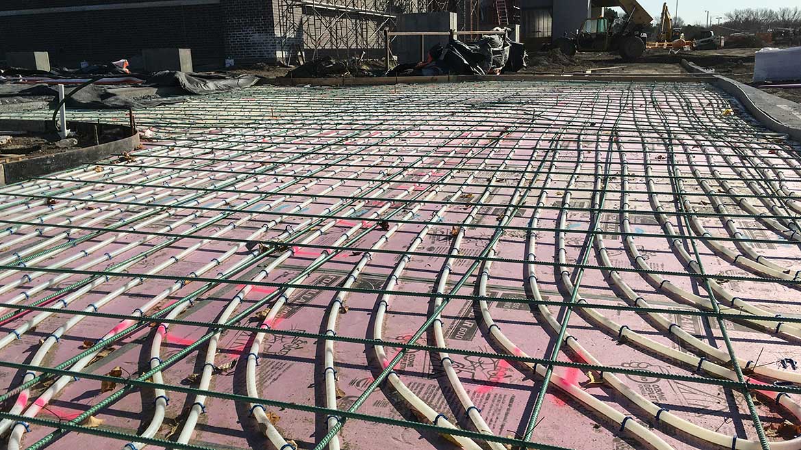
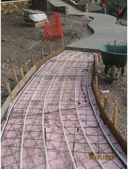
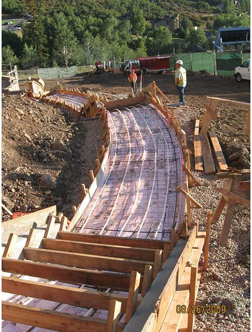
There are various slab constructions used in commercial snow and ice melting applications, including:
- Existing concrete with slab insulation, tubing tied to rebar, and concrete overpour;
- Base material with slab insulation, tubing tied to rebar covered in sand and topped with pavers;
- Base material with slab insulation, tubing tied to rebar covered in sand and topped with asphalt; and
- Suspended metal deck with tubing tied to rebar and covered with a concrete overpour.
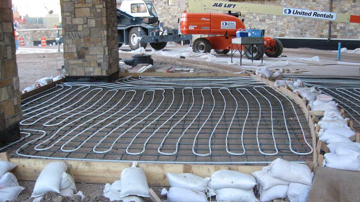
It is essential to coordinate with the building architect, structural engineer, civil engineer and landscape architect to ensure all parties are aligned on how the slab will be constructed, where the radiant tubing will be located in the slab, and how the slab may be impacted by the radiant tubing.
It is important to note that when designing a snow and ice melting system with suspended metal decking, downward heat loss must be considered. Since both the top and underside surfaces are exposed to the elements, there will be heat transfer in both directions, which makes insulation under the decking necessary.
System loads
Determining the system load is the next step in the design process, and there are a couple of different calculation methods. The first comes from Chapter 52 in the American Society of Heating, Refrigerating, and Air-Conditioning Engineers (ASHRAE) Applications Handbook. The second comes from the Snow and Ice Melting Design and Installation Manual, which is published by Uponor, a manufacturer of PEX radiant tubing.
There are several factors that can impact the design performance of the system, including air dry-bulb temperature, sky temperature, wind speed, humidity, snow density and rate of snowfall. When using the ASHRAE Handbook, Chapter 52 includes the design calculation that factors in the heat flux required at the snow-melting surface, the sensible heat flux, the latent heat flux, the snow-free area ratio, the convective and radiative heat flux from the snow-free surface, and the heat flux of evaporation.
The Snow and Ice Melting Design and Installation Manual from Uponor provides a more general approach that focuses on the required surface temperature for the system in combination with the outdoor temperature and wind speed to determine what the surface flux (Btu/h/SF) needs to be for the supply water temperature in tubing spaced at 6, 9, or 12 inches on center.
There are also online load calculators available through various manufacturer representatives which can also provide this information.
Be sure to locate the manifolds as close as possible to the area they are serving to help provide the greatest system efficiencies and performance.
System design
After determining the load, the next step in the process is the system design, which includes parameters such as tube spacing, operating water temperatures, flow rate, manifold sizing and manifold locations.
Rules of thumb for snow and ice melting systems design parameters include:
- Minimum surface temperature of 33° F;
- Typical target snow melting temperature of 38° F;
- Maximum water temperature of 150° F;
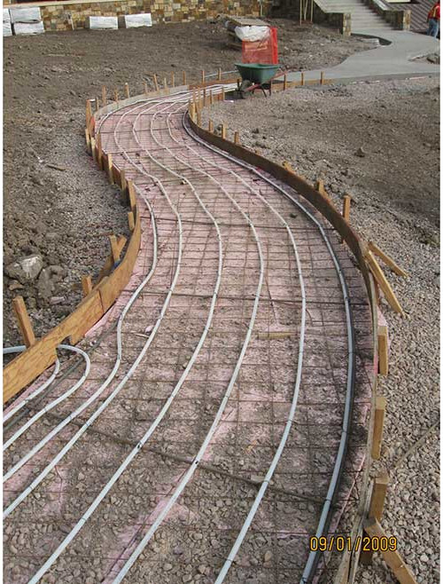
- Spacing at 6" on center;
- Loop lengths of 300 to 500 feet;
- Pipe sizes of 5/8 inches or 3/4 inches;
- Design differential temperatures of 25° F; and
- Propylene glycol at 50% maximum.
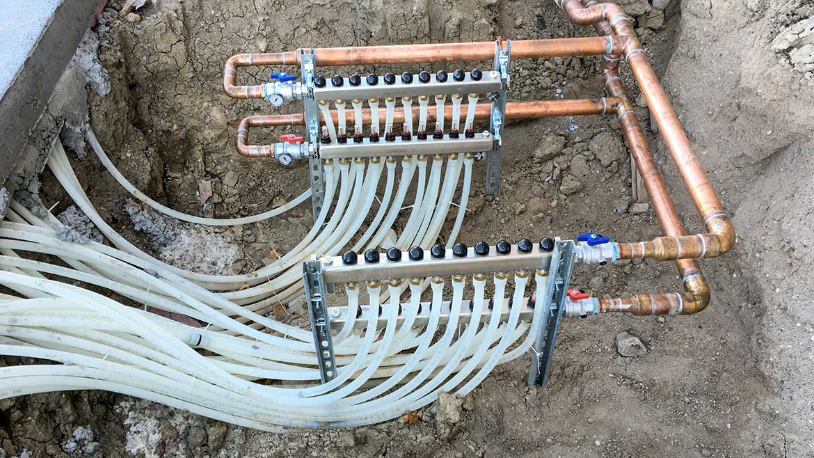
When it comes to sizing and locating the manifolds, it is important to coordinate with the building architect and the landscape architect to ensure all parties involved are on the same page about where the manifolds are going to go in the design. Be sure to locate the manifolds as close as possible to the area they are serving to help provide the greatest system efficiencies and performance.
When deciding which type of manifold to use, refer to the manufacturer’s submittal or spec sheet to determine the total gallons per minute (gpm) flow. Typical radiant manifolds can provide anywhere from 21 to 48 gpm total flow with 2 to 4 gpm per loop.
Additionally, because the manifolds are typically located in remote areas away from the boiler plant, it’s important to choose the proper piping solution for transporting the heating hot water supply and return. A couple of good sustainable options include Ecoflex, which is a flexible pre-insulated piping system with PEX service pipe surrounded by layers of closed-cell foam insulation and covered by a corrugated HDPE jacket. There is also PP-RCT pipe, which is available with a middle fiber layer which helps minimize linear expansion and contraction that occurs with polymer piping systems.
When deciding which type of manifold to use, refer to the manufacturer’s submittal or spec sheet to determine the total gallons per minute (gpm) flow. Typical radiant manifolds can provide anywhere from 21 to 48 gpm total flow with 2 to 4 gpm per loop.
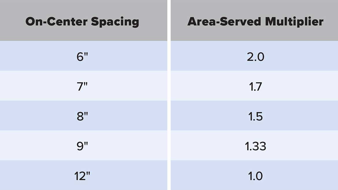
To determine the proper amount of tubing needed, simply refer to the table below for the area-served multiplier and then follow the simple calculation of Area times 12 divided by the Spacing (Tubing Length = Area X 12 / Spacing).
Table 1:
Control strategies
There are three main control strategies for snow- and ice-melting systems. The first is constant idle operation, where the system idles when the ambient temperature drops below freezing. It maintains a 32° F surface temperature and can be modified to use predictive weather data.
The second strategy is semiautomatic, which is similar to constant idle but is user-initiated. The system is designed to reach target surface temperature and then time out. This strategy requires the use of a slab sensor to monitor the temperature of the slab to ensure it stays at the proper temperature.
The third strategy is an automatic system that starts based on the detection of snow or ice via a slab sensor or aerial sensor. This strategy typically incorporates an idling sequence to increase the system response time.
Construction documents
Finally, to ensure the system gets installed the way it was designed, it is important to provide plans that include the following:
- Clearly defined zones with coordinated manifold locations;
- Site distribution piping;
- Pumps/boilers;
- Piping schematic;
- Control diagram with sequence of operations;
- Schedule; and
- Details.
To learn more about hydronic radiant snow and ice melting systems or for design support, contact your local PEX manufacturer representative or visit uponor.com.


