
No matter the square footage or gpm of a roof drain design, a 2-inch water dam is provided standard. Scuppers are really the only time any consideration is taken with the height of ponding before cascading off the side of the building.
Some AHJs, Oklahoma State for instance, safeguard their cities by requiring a 10.2-inch rainfall rate to be used for sizing overflows as a response to past roof collapses. The same increased protection can be seen when designing a project to FM Global Standards, requiring the overflow to be sized twice the 100-year, 60-minute rainfall intensity; however, neither Oklahoma nor FM Global take the overflow water dam height into account.
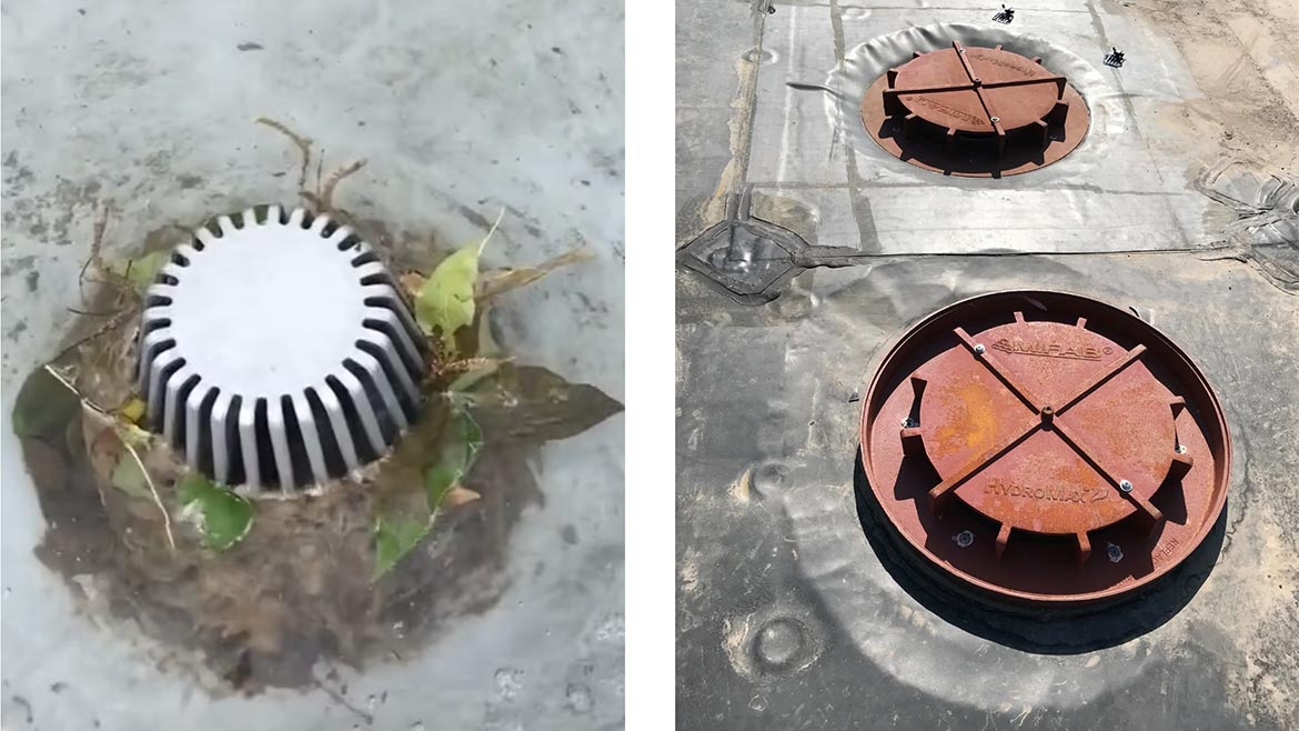
An example of clogged roof drains.
During an ASME A112.6.9 performance test to certify a siphonic drain, a ponding curve is created. Each drain has its own unique ponding curve. Based on the gpm design for the drain on the roof, we can understand what the ponding depth would be for the siphonic drain to reach full siphonic mode — zero air in the system.
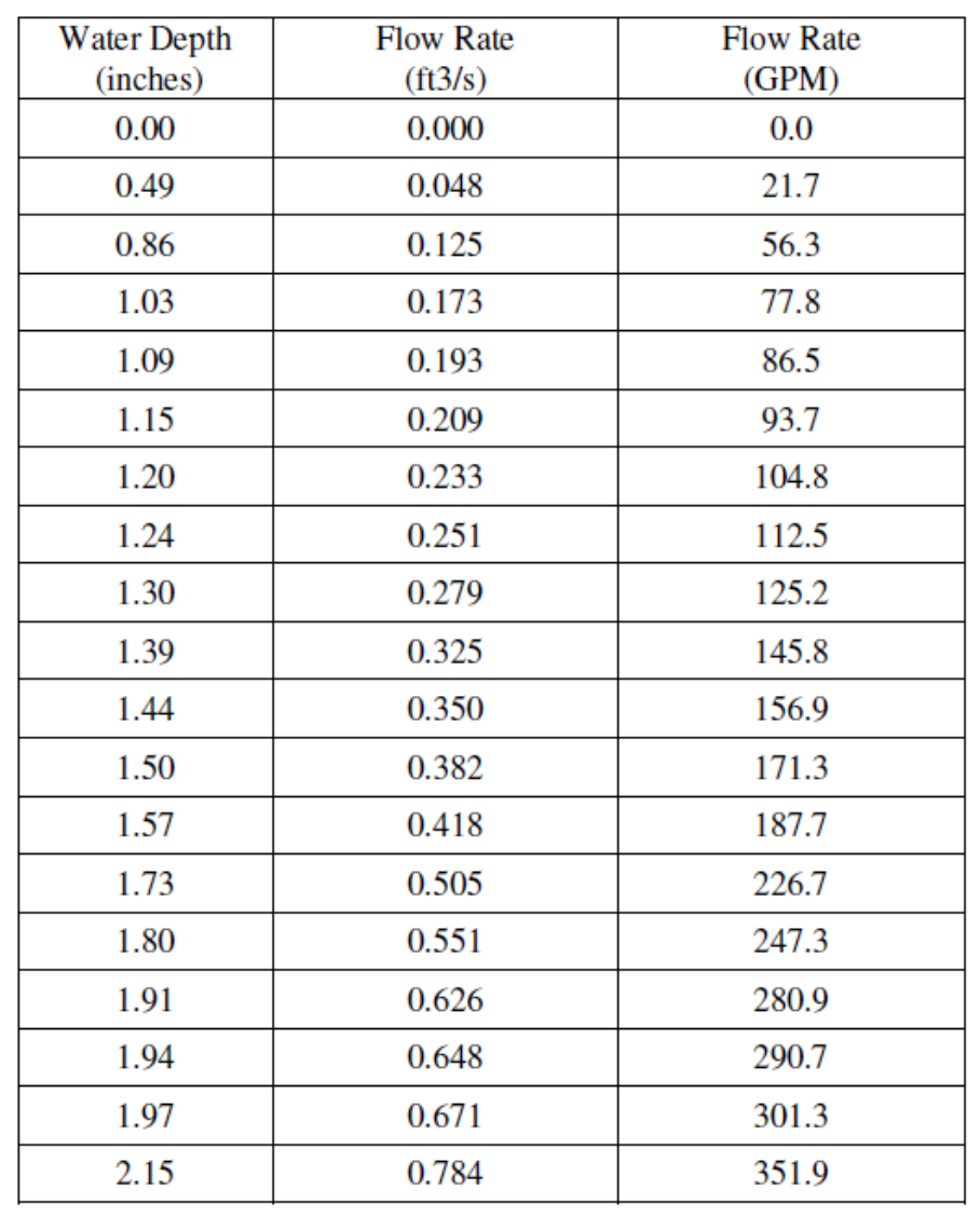
TABLE 1
**MH-300 Ponding Curve
In Table 1 (above): If a MH-300 is designed for 175 gpm (5,615 SF at 3” rainfall rate), we would expect 1.55 inches of ponding when the system enters full siphonic mode. The entire pipe system is 100% full of water at that point.
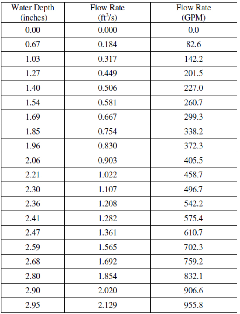
TABLE 2
** MH-600 Ponding Curve
In Table 2 (above): If a MH-600 is designed for 900 gpm (28,875 SF at 3-inch rainfall rate), we would expect 2.89 inches of ponding when the system enters full siphonic mode. If we used a standard 2-inch water dam, the overflow would engage constantly. For this project, a 3-inch water dam would be recommended to allow the system to reach full siphonic mode before the overflow would have the potential to engage.
If the design wanted to keep a 2-inch water dam standard, more drains should be added to get below the 300 gpm mark.
This issue is not that siphonic drains pond more than gravity drains, quite the opposite. Siphonic drains will ALWAYS have less ponding than traditional gravity drains.
TABLE 3
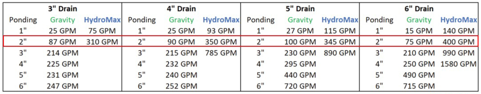
**MIFAB Data
Gravity drains require 2/3 air mixing with 1/3 water to transport efficiently. Siphonic drains have a baffle plate eliminating air from entering the pipework; without the need for air the pipe diameter is roughly ½ the size in a siphonic system.
For gravity drains, once the ponding reaches a point where the weir collapses (and there is no longer air getting to a gravity drain), the gravity drain starts losing efficiency, ponding at a quicker rate.
TABLE 4
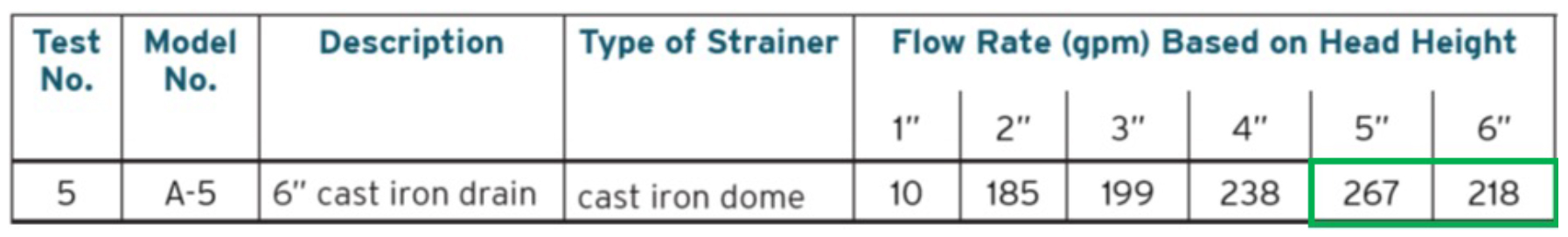
**ASPE Research Foundation 2012: Storm Drainage System Research Project
The increased ponding is also created when the leaves and debris collect on the side of a gravity drain which ultimately leads to roof drain leaks, failures, and eventual roof collapse.
Siphonic drains provide the data to make an informed decision on water dam heights, leading to safer buildings. The siphonic drain’s efficiency compliments the design advantage of installing the pipe flat at half the diameter of traditional gravity drainage. Designers can create simpler and more streamlined drainage plans which can save time and money in the design phase, as well as in the construction phase.
As the desire to create safe buildings will always be top priority, siphonic drainage will continue to be seen on projects as building owners increasingly become educated.

