
One of the biggest “game changers” for the North American hydronics market is the increasing availability of air-to-water and water-to-water heat pumps. In addition to heating, these heat pumps can produce chilled water for cooling.
When a fixed output heat pump supplies a highly zoned heating or cooling distribution system, a buffer tank is typically used to prevent the heat pump from short-cycling under very low load conditions.
In a heating-only system, the buffer tank can be set up with several possible piping configurations. One of my favorites is the “3-pipe configuration” shown in Figure 1.
Figure 1
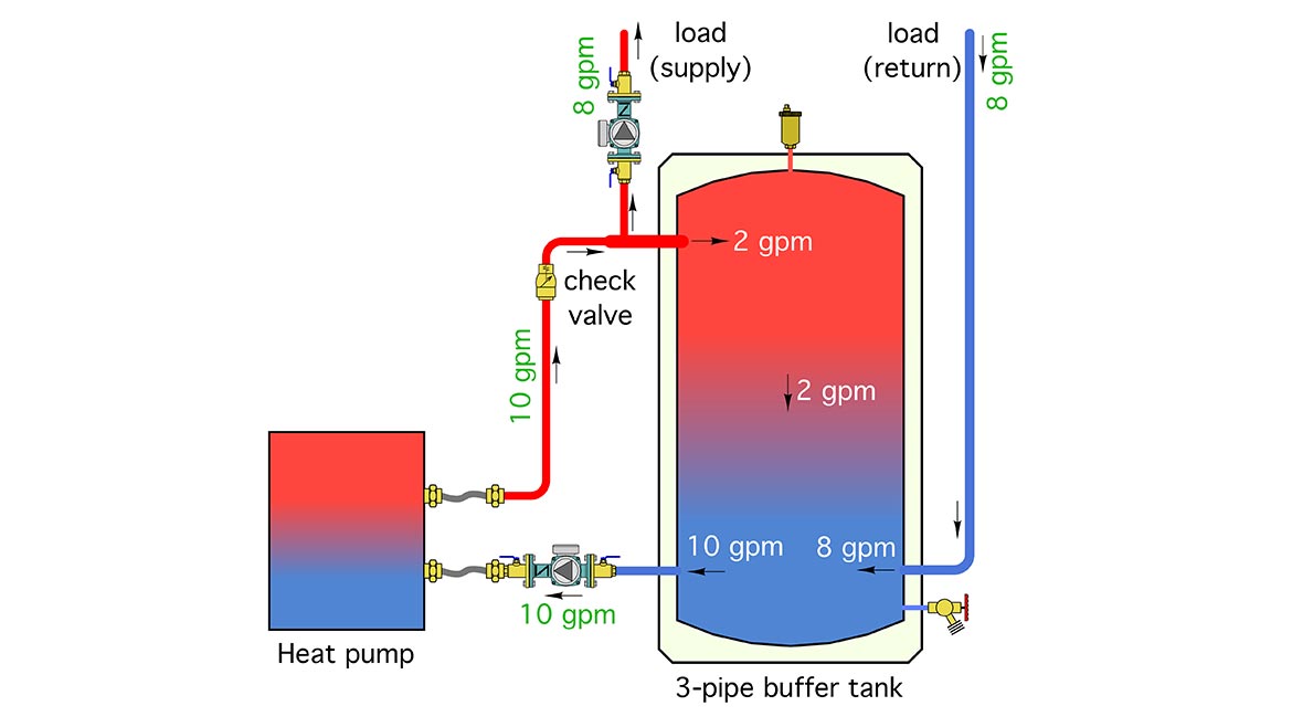
This piping allows “direct-to-load” heat transfer, which happens when the heat pump and load are operating at the same time. Any difference between the flow rate through the heat pump and the flow rate to the load is routed into or out of the buffer tank. For example, if the flow rate from the heat pump was 10 gpm and the flow rate to the load was 8 gpm, then 8 of 10 gpm would flow directly from the heat pump to the load, and the remaining 2 gpm would flow into the upper portion of the buffer tank.
Flow returning from the load passes through the lower portion of the tank, and eventually back to the heat pump. This keeps the thermal mass of the tank “engaged,” which helps provide longer (but fewer) cycles for the heat pump.
When the tee connecting the heat pump, tank and load is placed close to the tank, that latter also provides hydraulic separation between the heat pump circulator and the load circulator.
Layered up
Piping that allows the hottest water to interact with the top of the tank while cooler water passes through the lower portion helps preserve temperature stratification within the tank. A well-stratified tank is thermodynamically superior to a fully mixed tank. There are some complex calculations that prove this, but a short thought experiment based on Figure 2 will lead you to the same conclusion.
Figure 2
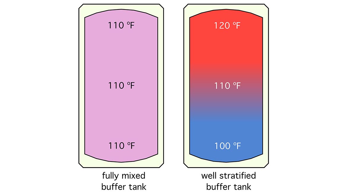
The tank on the left is fully mixed. All the water it contains is at 110° F. The tank on the right is an identical tank, but with 120° F water at the top and 100° F water at the bottom. Assuming a symmetrical temperature profile top to bottom, its average temperature is also 110° F. From the standpoint of thermodynamics, both tanks contain the same amount of heat.
However, the tank on the right could supply a load that required 120° F, or 119° F, or even 111° F water, at least for a short time, whereas the fully mixed tank, technically, could not supply a load that required more than 110° F. Arguably, these differences are small and likely short-lived, but nonetheless, they show that a well-stratified tank has a slight advantage in terms of its potential “usefulness” in meeting the temperature required by a thermal load.
Maintaining temperature stratification within a thermal storage tank takes planning. It’s essential to create conditions that minimize mixing within the tank. Incoming flows, in particular, must enter with minimal velocity, in a horizontal direction, and, ideally, at locations where the density of the incoming water is as close as possible to the density of the water in the tank. Compromise on these ideals is usually necessary.
What about cooling?
Although the “hot at top/cool at bottom” buffer tank piping is ideal for heating, there are systems where the buffer tank will also be used for chilled water storage during the cooling season. This scenario is common for systems that have extensive zoning of the cooling distribution system along with single speed heat pump.
Systems using a single chilled water air handler, combined with a variable speed heat pump usually don’t require a buffer tank for cooling mode operation. The controls on the heat pump can be set for a desired leaving chilled water temperature and the compressor adjusts speed and cooling capacity to maintain that temperature. However, if some of the zone cooling loads are below the minimum cooling capacity of the heat pump, a buffer tank is still a good idea.
Due to its higher density, the lowest temperature water “tries” to collect at the bottom of the buffer tank. To maximize the cooling capacity of an air handler or fan coil, chilled water should be supplied from the lower portion of the tank.
This obviously creates a complication if the tank is piped based on maintaining temperature stratification in heating mode, and the near-tank distribution piping is common to both heating and cooling distribution.
One way to handle this situation is to use two buffer tanks, one for heating and the other for cooling. The downside is the cost of the second tank as well as a larger mechanical room footprint. Still, 2-tank design make sense in buildings with simultaneous heating and cooling loads. Those buildings are usually large enough to require multiple heat pumps. The piping and control for such a system will be covered in an upcoming column.
Another option is to use two 4-way “reverser” valves operated by motorized spring-return actuators. An example of such a valve and actuator is shown in Figure 3.
Figure 3
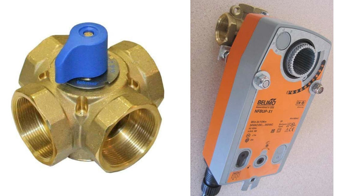
The 4-port valve body is intended for a mixing application. It has an internal vane mounted to the spindle. In a mixing application, it blends boiler water with water returning from the distribution system to create a desired supply water temperature. It also blends boiler water and return water to boost the boiler inlet temperature to prevent a conventional boiler from operating with sustained flue gas condensation. Figure 4 shows both extreme positions of the internal vane, as well as a position where mixing simultaneously reduces supply water temperature relative to boiler outlet temperature, and boosts boiler inlet temperature.
Figure 4

“Off-label” application
Fortunately, this body construction can also be used as a 2-position reverser valve. It can be coupled to a 2-position spring-return actuator. When the actuator is powered, it rotates the vane to one of the 45° positions shown in Figure 4. When the actuator is off, its internal spring rotates the vane to the other 45° position. Spring-return actuators are available for several operating voltages such as 24VAC and 120 VAC.
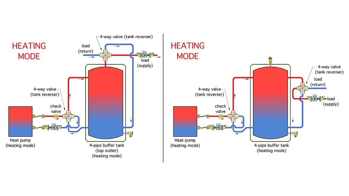
When two of the valve + actuator assemblies are combined with the piping shown in Figure 5, the flow direction through the buffer tank can be reversed, while the flow direction through the heat pump and the distribution system remains the same.
Figure 5
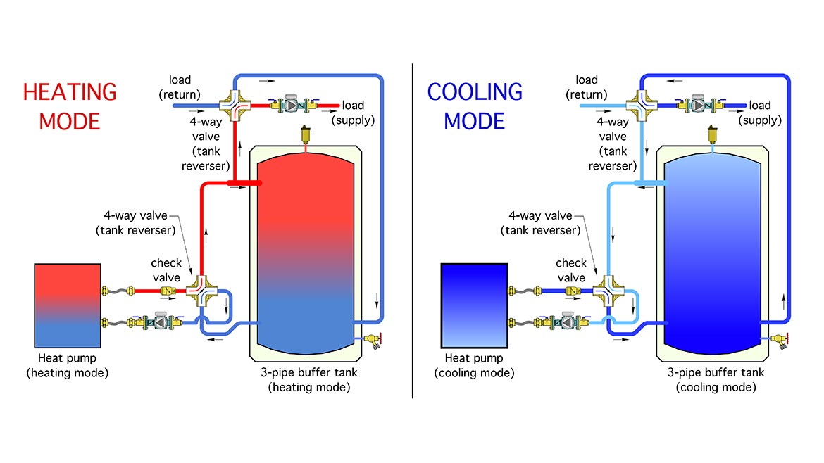
This piping arrangement allows the hottest water from the heat pump or upper portion of the tank to be routed to the heating load. It also allows the coolest water from the heat pump or lower portion of the tank to be routed to the cooling load.
Both modes provide for horizontal inlet flow to all tank connections, which helps preserve temperature stratification. Both modes also allow the tank to provide hydraulic separation between the heat pump circulator and the load circulator. Either circulator could be fixed speed or variable speed.
One variation on this concept would be to couple both 4-way valve bodies to a common actuator shaft. Another would be to combine the reverser valves with variations in tank piping such as shown, for heating mode, in Figure 6.
Figure 6
Another “plausible” variation on the concept is to eliminate the actuators, and instead count on someone on site to manually turn the valves between the heating and cooling position on a seasonal basis. This would reduce cost, but obviously must be done consistently. If you’re considering this, be sure to talk it through and get commitment from the owner.
A few other details are worth mentioning:
1. It’s critically important to insulate and vapor seal all piping and components conveying chilled water to prevent surface condensation. There’s no “cheating” when it comes to this insulation. Missing or poorly installed insulation allows condensation to form, with drips, puddles and corrosion of any ferrous metals soon to follow. Not convinced? Take a look at the uninsulated circulator volute in Figure 7 which has only operated through two cooling seasons.
Figure 7
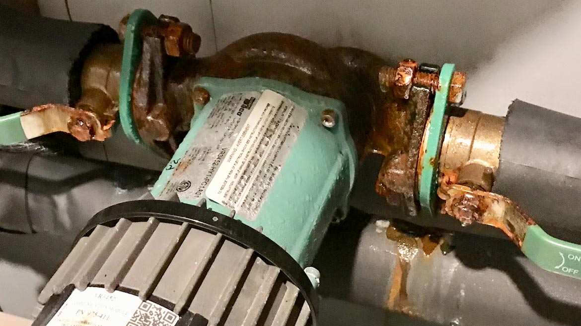
I can assure you that this corrosion is “brand agnostic.” If it’s iron, and it’s not insulated from the surrounding air, and it conveys chilled water, it’s going to rust.
2. A spring check is shown in the piping leading from the heat pump to the tank reverser valve. It’s there to prevent reverse thermosiphoning when the tank is heated, but the heat pump is off. Check valves within small circulators would help in this respect, but not all circulators have these valves.
3. This concept is highly scaleable and could be used with residential or commercial systems. 4-way valves are currently available up to at least 4-inch pipe size.
4. This concept can work for either air-to-water heat pumps or water-to-water heat pumps.
Value engineering
It should be noted that 4-way valve bodies are quite a bit less expensive than tanks. The piping and fittings involved with the two valve assemblies versus those if two tanks are used are likely comparable. Perhaps you can apply this concept on a future heat pump project.


