
The vast majority of solar-thermal collector installations place the collectors at a slope.
One rule of thumb that has been in the solar-thermal industry for decades is that using a collector slope angle (measured upward from horizontal), and equal to local latitude, optimizes the annual solar-energy incident on the collectors, when the collectors face due south. Since domestic water heating is a year-round load, most collectors used in solar DHW systems are installed with a slope that’s within a few degrees of local latitude.
In applications where the dominant load is space heating and the goal is to maximize winter energy collection, a collector slope of (local latitude +15°) often is used. In addition to maximizing winter solar gain, steeper slopes enhance the ability of the collector to shed snow.
Steeper collector angles also reduce energy collection during summer. That might seem contradictory given that maximum solar energy availability occurs in summer. However, unlike net-metered solar-photovoltaic systems that send surplus energy back to the utility grid, solar-thermal systems have to do something on site with any surplus heat.
In some systems, the controls just turn off the collector circulator when the storage tank reaches an upper setpoint such as 180º F. When several sunny days with high afternoon air temperatures occur in succession, and if the system doesn’t have a means of dumping surplus heat, there are going to be times when the antifreeze fluid stagnates in the collectors. Under those conditions that fluid could reach temperatures in excess of 300º. Such temperatures cause rapid deterioration of antifreeze solutions, turning them into a nasty acid sludge.
In systems using drainback freeze protection, the collectors drain out when the upper temperature limit of the tank is reached and thus there’s no concern about fluid degradation or boiling. Solar collectors tested to the OG100 standard from the Solar Rating and Certification Corp. (SRCC) must withstand a dry stagnation test for a minimum of 30 sunny days. Still, there’s no getting around the fact high stagnation temperatures eventually take their toll on the collectors’ elastomeric seals and insulation.
There are several ways to install collectors at relatively steep angles. One approach is to mount the collectors to a ground-support frame that’s specifically designed to hold them at a steep angle, such as the array shown in Figure 1.
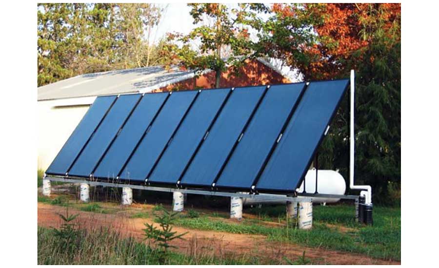 Figure 1. One approach is to mount the collectors to a ground-support frame that’s specifically designed to hold them at a steep angle, such as the array shown here. Photo courtesy of Cardinal Heating & Air Conditioning.
Another common approach is to mount the collectors on a southerly-pitched roof, propping up their rear edge to the desired slope using a mounting kit such as shown in Figure 2.
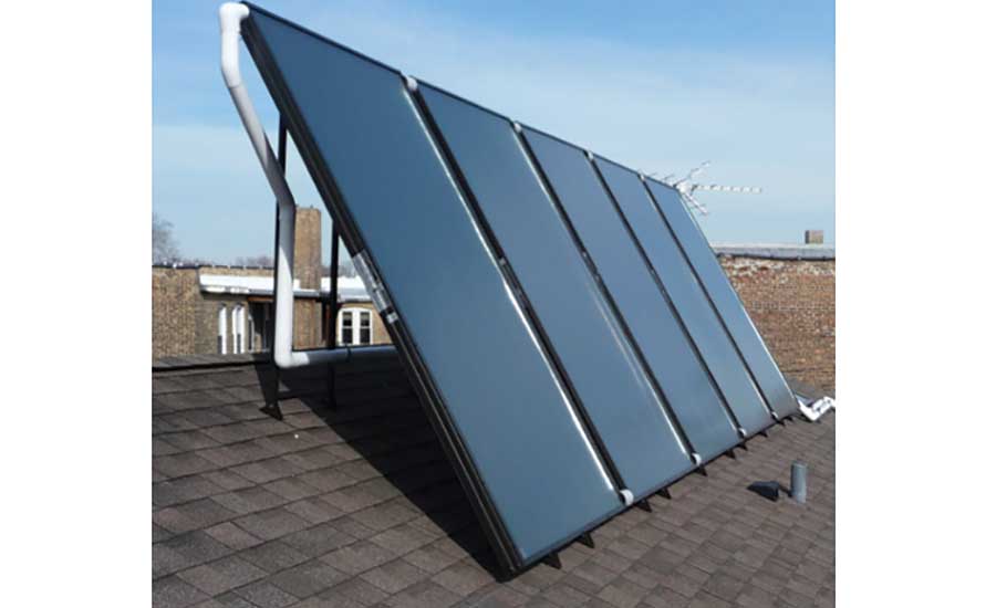 Figure 2. Another common approach is to mount the collectors on a southerly-pitched roof, propping up their rear edge to the desired slope using a mounting kit such as shown here. Photo courtesy of Solar Service.
Although the latter method produces the desired slope, it also could be seen as compromising the aesthetics of the building. Collectors mounted at a steep angle on an average roof slope, especially when the project is up over the roof ridge, can be subject to strong wind loads. It’s essential all hardware connects into building framing using generously sized stainless steel hardware.
In rare cases, the building roof might be constructed at a steep angle that allows the collectors to be flush mounted, as in Figure 3.
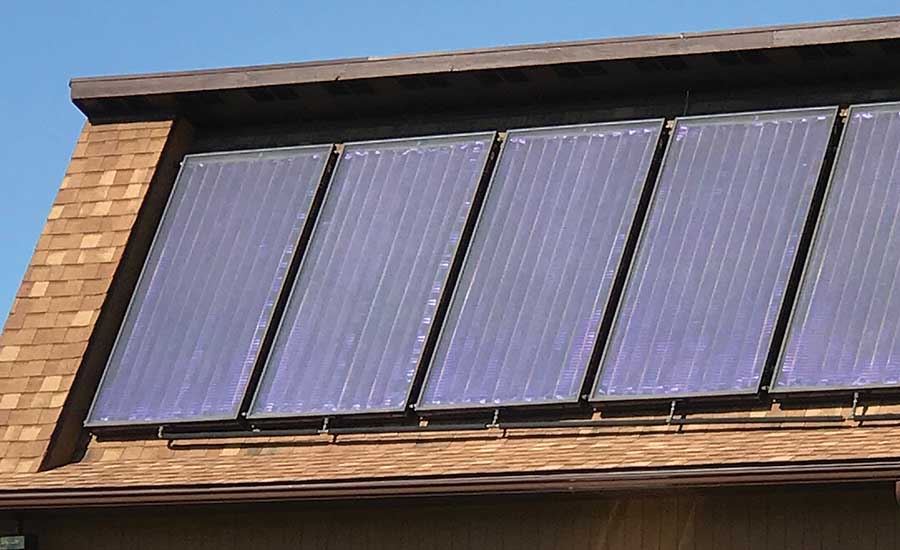 Figure 3. In rare cases, the building roof might be constructed at a steep angle that allows the collectors to be flush mounted, as in this example here. Photo courtesy of Solar Service.
One might argue building the roof to accommodate the collector slope also is an aesthetic compromise. The old saying that “beauty is in the eye of the beholder” always will be appropriate.
The highest collector slope angle is 90°. Based on the rule of thumb for space-heating applications, (slope = latitude + 15º) this angle would be appropriate for latitudes of 75º. That puts you up in the Arctic Ocean well north of Alaska. I don’t imagine the solar-thermal market is strong up there.
But what about sloping a collector at 90º in more hospitable climates? The obvious question is how would that slope affect the annual thermal performance of the system relative to the (slope = latitude + 15º) scenario?
Run the numbers
To address this, I used f-Chart software. The system I modeled is for domestic water heating and partial space heating of a house with a design space-heating load of 30,000 Btu/h in Syracuse, N.Y. The DHW load is 60 gal. per day heated to 125º. I assumed the collector array faced directly south and consisted of five, nominal 4-ft. by 8-ft. flat-plate collectors (single glass/selective surface, Y-intercept = 0.74, slope = -0.74). This describes the collector array shown in Figure 3.
The system includes a thermal storage tank with a volume of 2 gal. per square-foot of collector. The f-Chart software was run for collector slopes of latitude +15º (58º in Syracuse) and for vertical (e.g., slope = 90º). Figure 4 shows the monthly percentage of the total load (space heating + DHW) supplied by the solar-thermal system at each of the collector slope angles.
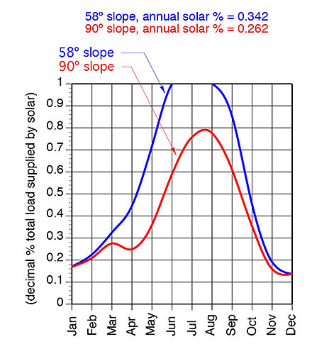
Figure 4. Shows the monthly percentage of the total load (space heating + DHW) supplied by the solar-thermal system at each of the collector slope angles.
The system with the 58º collector slope is estimated to supply 34.2% of the total thermal load (space heating + DHW) of the building. The system using 90º sloped collectors provided 26.2% of that same load. The difference in auxiliary energy used was about 6.6 MMBtu. In the Syracuse area, heat supplied from a mod/con boiler burning natural gas at an average efficiency of 92% runs about $20/MMBtu. So the projected additional auxiliary energy cost associated with the vertical collector array would be about $132 per year.
The system with 58º sloped collectors supplies more than 100% of the load in June, July and August. Although f-Chart doesn’t report the amount of excess energy, you can be sure this system would experience conditions where excess heat dissipation is necessary. If the system used antifreeze-based freeze protection, a heat dump would be essential.
The vertically sloped array yields lower output in summer in comparison to the 58º sloped array. However, it still provides between around 70% of the summer (DHW) load.
Notice that the differences in percentage of load supplied in the typically “low solar” months (January, February, October, November and December) is much less than the differences during the “high solar” months.
The “dip” in the red curve for the vertical collector array is based on the reflectively of the ground surface changing from 0.8 during months with assumed snow cover (December through March) and an assumed ground reflectively of 0.2 for months without snow cover. The vertical collector array definitely benefits more from higher ground reflectance in comparison to the 58º sloped array.
The fact the solar fraction curve for the vertical array doesn’t hit 1.0 (e.g., 100% of the load) should not be interpreted to mean the system will never produce excess heat. Imagine, for example, three hot and sunny summer days in succession, while the family is on vacation, and thus there is no DHW or space-heating load. Still, the expected frequency of excess heat situations definitely will be less for the vertical array.
One more spin
Since the thermal performance of the vertical collector array was, as expected, lower than the 58º sloped array, I decided to run the simulation of the vertical array one more time, but with one additional 4-ft. by 8-ft. collector. The results are shown in Figure 5.
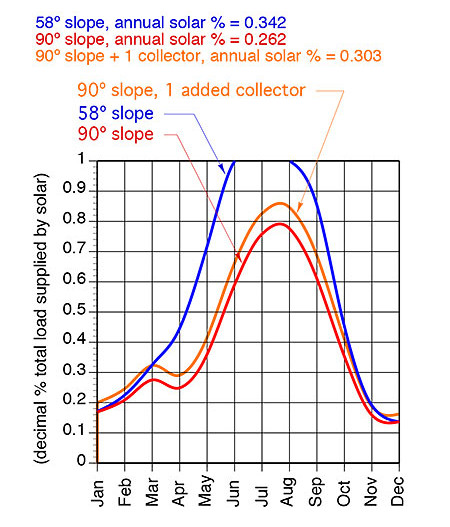
Figure 5. I decided to run the simulation of the vertical array one more time, but with one additional 4-ft. by 8-ft. collector. The results are shown here.
As one would expect, the larger array gathers more energy in both winter and summer. Perhaps less expected is the added collector allows the vertical array to gather slightly more energy during early winter (e.g., January into March) and again in late fall (November into December) in comparison to the 58º sloped array. It does so while still staying below the 1.0 solar fraction during summer.
Here’s a thought: Would installing six 4-ft. by 8-ft. collectors on a vertical wall, perhaps close to finish grade, cost less than installing five of the same collectors at 58º on a sloping roof? It might, depending on roof height, slope, roofing material, piping pathway through attic, distance from collector to storage tank, etc.
Straight up benefits
Vertical collectors certainly are less likely to be impaired by snow accumulating on their glazing. This is especially beneficial when evacuated tube collectors are used, as shown in Figure 6.
 Figure 6. Vertical collectors certainly are less likely to be impaired by snow accumulating on their glazing. This is especially beneficial when evacuated tube collectors are used, as shown here. Photo courtesy of Revision Energy.
The high vacuum in the glass envelope of an evacuated tube collector keeps the outer surface very close to ambient air temperature. This makes the tube relatively ineffective at melting snow when the sun is out but air temperatures are below 32º.
Vertically-mounted collectors trade roof-penetration flashings for wall penetrations. The latter are less prone to long-term leakage.
In many cases, collectors mounted to walls eliminate the need to work with piping or structural reinforcement within attic spaces.
Wall-mounted collectors also remove concern over having to eventually replace the roofing materials under the collector array. This is not a major concern with new roofs, but can be when collectors are installed over shingles that are perhaps 20 years into a projected service life of 25 years.
With detailing such as color-matched flashing over piping, between collectors and around the perimeter, an array of vertical collectors can become an attention-getting architectural feature for the building. Probably not at street level in a city, but, well, you get the idea.
Figure 7 shows an array of flat-plate collectors mounted on a south-facing wall in Santa Fe, N.M.
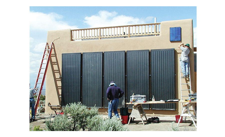 Figure 7. Shows an array of flat-plate collectors mounted on a south-facing wall in Santa Fe, N.M. Photo courtesy of SolarLogic.
Think about it
If you have opportunity to design a solar-thermal combi-system for a building in a cold northern climate, consider vertical collector mounting. It may not produce the maximum energy capture on an annual basis, but the energy it does collect is more likely to be in line with the combined space heating and DHW needs of the building and less likely to send significant energy to a heat dump in summer.
To read Siegenthaler’s article “The case for vertical collectors” in pdf form, please see here.


