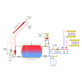
Figure 1.
Nearly all solar thermal combisystems have a large, insulated tank that stores heat gathered from the collectors. The water temperature in this tank varies considerably from hour to hour depending on solar input (or lack thereof), as well as heat extraction by the load(s).
When there is a demand for space heating, the control subsystem must decide if the tank is warm enough to supply the load. If not, it must enable operation of the auxiliary heat source. When a low-temperature hydronic distribution system is used, that auxiliary heat source is often a modulating/condensing boiler.
Figure 1depicts a typical space-heating system in which a closed-loop collector array operating with antifreeze and a heat exchanger supplies a large (pressurized) thermal storage tank. The piping on the right side of this tank allows either that tank or the auxiliary mod/con boiler to supply the low-temperature radiant-panel distribution system. For the time being, this schematic has no subsystem for domestic water heating. We’ll add that shortly.
Upon a demand for space heating from any heating zone, an outdoor reset controller is powered on to measure the temperature at the top of the storage tank, and compare it to a calculated “target” supply water temperature. If the tank is deemed sufficiently warm to supply the zones, circulator (P2) is turned on to deliver heated water to the closely spaced tees that hydraulically separate the distribution system from the heat sources. If the storage temperature is too low to supply the load, the auxiliary boiler is turned on along with circulator (P1). Again, heated water is delivered to the closely spaced tees and carried onward into the distribution system by the variable-speed, pressure-regulated circulator.
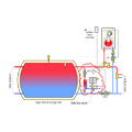
Figure 2.
Adding DHW
Figure 2shows one way to extend the system shown in Figure 1 to leverage the thermal mass of the storage tank for preheating (or fully heating) domestic water on an “instantaneous” basis.A flow switch detects whenever domestic water is required at a flow rate of 0.5 gpm or above. Under this condition, it turns on a small circulator that moves heated water from the storage tank through the primary side of a stainless-steel, brazed-plate heat exchanger. Cold water is instantaneously preheated (or fully heated depending on the tank temperature) as it passes through the other side of the heat exchanger.
An electric tankless water heater provides any necessary boost in domestic hot water delivery temperature. An anti-scald-rated thermostatic mixing valve protects against high domestic water temperatures when the storage tank is at an elevated temperature. For the fastest possible response, the piping between the storage tank and heat exchanger should be short and fully insulated. This configuration allows for preheating domestic water whenever the storage tank is above the temperature of the entering cold domestic water.
.jpg)
Figure 3.
Extracting More Heat
One limitation of this basic control logic is there is no operating mode whereboththe storage tank and auxiliary boiler can supply heat to the load.Consider the situation where the temperature at the top of the storage tank is slightly lower than the lower limit established by the outdoor reset controller,but still warmer than the return temperature of the distribution system. Under these conditions, the tank can still contribute some heat to the space-heating load. The remaining heat would be supplied by the auxiliary boiler.
The addition of a second differential temperature controller (abbreviated as ∆T controller), like that used to control the solar subsystem, allows the storage tank to be used at a lower temperature.Figure 3shows where the sensors for this ∆T controller would be located.Figure 4shows a ladder diagram containing the hard-wired logic for the overall system.
If the outdoor reset controller determines the tank is too cool to supply the load, its normally open contact closes to power up the ∆T controller as well as a relay that enables the boiler to operate and places control of circulator (P2) solely at the discretion of the ∆T controller.
The ∆T controller measures the temperature difference between water at the top of the storage tank and that returning from the distribution system. If the top of tank is at least 2º F above the return temperature, the normally open contact in the ∆T controller closes to keep circulator (P2) operating.
The boiler and circulator (P1) also are operating at this time. The boiler is monitoring the temperature downstream of the closely spaced tees. Ideally, it modulates to add just enough heat to maintain this temperature close to the target temperature required by the distribution system, based on the settings of its internal reset controller.
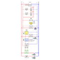
Figure 4.
If the temperature difference between the top of the storage tank and the return side of the distribution system drops to less than 1° F, there is very little heat being extracted from the tank. Under this condition, the ∆T controller turns off circulator (P2) to prevent heat supplied by the auxiliary boiler from being added to the storage tank. The auxiliary boiler and circulator (P1) remain on to supply the space-heating load as required.
When the storage tank temperature again rises to where the temperature differential between the top of the tank and the return side of the distribution system reaches 2° F or more, the circulator (P2) is turned back on to again extract available heat from the tank.
This strategy makes sense when a large storage tank is used in the system. I suggest it only be used when the storage tank contains at least 500 gallons. The ability to lower 500 gallons of water by an additional 10º F implies a release of almost 42,000 additional Btu from the tank. Smaller tanks would contribute proportionally smaller amounts of heat, and thus provide less justification for the additional controls.
If you implement this strategy, be sure the temperature sensors for the ∆T controller are mounted in identical or nearly identical manners. Ideally, both sensors would be mounted in identical sensor wells, immersed in the system water, and with ample coatings of thermal grease. If mounted to the surface of copper tubing, be sure the sensor surface makes good contact, is well-secured and is fully wrapped with insulation.
Remember, you’re asking the ∆T controller to detect differences in temperatures as low as 1° F. That’s about 1/3 the temperature difference you can detect with your own fingers.


