Lower heat loads make more design options available.
Preparing an accurate heat loss or a peak design heating load calculation is the foundation of an efficient and effective radiant heating system. I say “efficient and effective” because before the mid 1980s, when the modern wave of radiant heating found its roots, sizing a heating system was more an art than a science. It was hard to find any boiler with a Btu/hr output of less than 125,000, and the controls that regulated many hydronic systems were limited to a single (line voltage) thermostat, operating high-limit aquastats and a BIG pump.
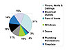
Figure 1.

Selection of appliances and controls will maximize the energy efficiency of domestic water production while integrating space heating.
I once tried to sell a radiant heating system to a builder whose project was a showcase for green building technology. He coined one of my favorite heating-related sound bites: “The best heating system is the one that never comes on.”
I was puzzled and asked how this was possible. He answered that his 3,500-square-foot home had a high-performance building envelope. As part of determining a net heat loss, every internal source of heat gain had been factored in, and a high-efficiency heat recovery ventilator would recover the majority of the exiting Btu out of the ventilation air.
The total heat load had been calculated meticulously to be a mere 18,500 Btu/hr. From this example it is easy to see that we have moved to an era when sizing a system is now a science, and over-sizing the heating system would have been very easy to do.
Understanding how heat is lost from a building is essential to capturing all sources of heat loss and correctly determining the load requirements of our system. According to the Engineering ToolBox (www.engineeringtoolbox.com), the overall heat loss from a building can be calculated as:
H = Ht + Hv + Hi where:
H = overall heat loss (W)
Ht = heat loss due to transmission through walls, windows, doors, floors and more (W)
Hv = heat loss caused by ventilation (W)
Hi = heat loss caused by infiltration (W)
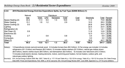
Figure 2.
According to the U.S. Department of Energy, 30.4% of our residential energy consumption is spent on space heating. This amount is estimated to be $76 billion in 2010. See Figure 2 below:

The exterior of an auto shop, which makes an excellent application for radiant heating.
Gather Needed Data
Before we can start to calculate the load, however, we need to gather the information relevant to our project. The normal source for this would be the plans and specifications (including the window/door schedules) issued by the architect or builder. Radiant Panel Association President Dorothy Biggs’ advice is simple, “Have an initial consultation meeting where all involved understand that changes to the building envelope or construction materials need to be recorded, and further that changes on the fly could be detrimental to system performance.”
Bill Shady, P.E., principal of Sustainable Designs and a partner in Pacific Solar Radiant, adds: “Accuracy is the key here. My design is based on the information supplied as of a certain date, and so I always reference that date in my design summary. If I model with windows of a certain U value and that value changes, or the amount of finished space increases, the builder must be sure I know about the change. At the end of it all, nothing beats a gut check; if from experience I expect to see a 20 Btu/hr per square foot output requirement and it’s 5 or 50, something’s wrong.”
What information is required in calculating a heating load?
-
Determine design temperatures (outdoor and indoor) to establish a Delta T∆.
-
Determine the construction of the building and the U values of its component parts or partitions (windows, walls, floors and ceilings) and calculate the area in square footage of the surface of these partitions.
-
Determine the appropriate number of air changes per hour or air change rate, which combines the losses resulting from both ventilation (Hv) and infiltration (Hi) and calculate the volume of the space in cubic feet. (Note: Stipulated requirements for forced ventilation are common in most jurisdictions, typically referring to ASHRAE Standard 62.1-2007 -- Ventilation for Acceptable Indoor Air Quality. Consult your local building code for further information.)
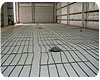
Interior shot of the auto shop.
Determine Design Temperatures
The National Climatic Data Center, an agency of the U.S. Commerce Department, publishes detailed weather data. From this information is derived the Winter Design Dry Bulb Temperature (or Outdoor Design Temperature) and the number of Heating Degree Days for a given location. While three occurrence values are tracked, the method taught in the RPA Radiant Basics course uses the 97.5% value, which is the temperature the outside air is at or above 97.5% of the year. The tables in Normative Appendix D, ASHRAE Standard 90.1- 2007 reflects the 99.6% values. The Indoor Design Temperature is generally accepted to be in the range of 68°F to 72°F with 70°F the recommendation from the RPA as shown in Figure 3.
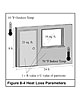
Figure 3.
In this example, our outdoor design temperature is -10°F and indoor design temperature is 70°F, thus our ∆T = 80°F, the net area of our R-19 wall is 155 square feet (less the area of door and window), the U value of that wall is U= 1/R19 or U 0.053 x 155 square feet = wall heat loss of 657 Btu/hr. After determining the U value for the door and window and repeating the same steps for each surface exposed to the outdoors, we come to a total surface heat loss of 4,750 Btu/hr. Assuming a room volume of 2,304 cubic feet (24x12x8) with an air change rate of 0.5 (a factor of 0.5 air changes per hour) the formula would be: Length x Width x Height x Design ∆T x .018 (the Air Change Factor) = 1,659 Btu/hr plus our surface loss of 4,750 = 6,409 Btu/hr as a total heat load.
It is apparent that in any context the integrity and thermal efficiency of the building envelope will determine how high or low our peak heating load will be. At first glance the example of a low total heat load discussed earlier would seem to be counter to the interests of those of us designing, selling and installing hydronic radiant heating systems, but I feel the opposite is true.
A lower heat load means that more options are available to the designer for types of fuel and appliance, and it further makes the integration of renewable energy sources more feasible. The future is represented in determining heat loss that is net of heat gain, for systems where the peak design load may be small, but not indicative of the comfort levels demanded by building occupants. Thus the actual system capacities may be higher by default than those dictated by peak design loads.
As you move forward from heat loss to system design consider this: In areas where the heating degree days are low, the heating load may be much smaller than the domestic water load as percentage of total energy consumption. This will further influence your appliance and control selections as you look to maximize the energy efficiency of the domestic water production while integrating space heating.


