

Figure 1.
In the August 2008 Solar Design Notebook column, we looked at the thermal efficiency of solar collectors. That efficiency can be represented as a graph, such asFigure 1.
The formula for the line on the graph has the following general form:
Formula 1:
Where:
=collector thermal efficiency
= intercept of the straight line
= slope of the straight line
Ti = inlet fluid temperature to collector (ºF)
Ta = ambient air temperature surrounding collector (ºF)
I = solar radiation intensity incident on collector (Btu/hr/ft2)

The thermal efficiency of solar collectors is verified through testing. The heat transferred to a fluid flowing through the collector can be calculated usingFormula 2:
Where:
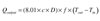
Q output = heat output of collector (Btu/hr)
c = specific heat of fluid flowing through collector (Btu/lb/°F)
D = density of fluid flowing through collector (lb/ft3)
f = flow rate through collector (gpm)
Tout = temperature of fluid leaving collector (°F)
Tin = temperature of fluid entering collector (°F)
8.01 = units conversion factor
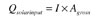
Formula 3:
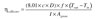
Formula 4
I = solar radiation intensity in the plane of the collector (Btu/hr/ft2)
Agross = gross area of collector as shown inFigure 2(ft2)
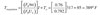
The collector’s thermal efficiency (Forumla 4) is found by dividing the thermal output (Formula 2), by the solar input (Formula 3):
Formula 4 is used to calculate the collector’s efficiency over a range of operating conditions. The constants (FRta) and (FRUL) are then determined by linear regression of efficiency numbers plotted as a function of the inlet fluid parameter (Ti-Ta)/I.
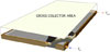
Figure 2.
Zero Efficiency = High Temperature
During its service life, every solar collector experiences a condition called “stagnation.” It occurs when solar radiation strikes the collector, but no fluid is flowing through the absorber plate. Stagnation can result from several causes, including: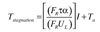
Where:
Tstagnation = stagnation temperature of absorber plate (°F)
This temperature might surprise some of you. It results from the fact that solar collectors are designed to maximize solar heat entry and minimize heat loss. Under stagnation conditions, the absorber plate climbs to whatever temperature is necessary so that the collector dissipates all the incoming heat by convective and radiative losses to its surroundings.
Surviving Stagnation
Solar collectors rated to the OG-100 standard established by the Solar Rating and Certification Corporation (SRCC) must undergo 30-day stagnation tests. During this test, collectors are subjected to 30 consecutive days where total daily solar radiation is at least 1,500 Btu/ft2/day in the plane of the collector, and at least one four-hour period with a minimum solar intensity of 300 Btu/hr/ft2. The average ambient temperature during this 4-hour severe stagnation period must be at least 80°F.After this exposure, collectors are visually inspected for any indication of insulation outgassing, pealing or flaking of the absorber coating, or other signs of degradation. Evidence of such degradation would disqualify the collector for the OG-100 certification.
The absorber plate isn’t the only thing that gets mighty hot during stagnation. If the collector is part of an antifreeze-based system, the fluid within the absorber plate is also getting cooked. In some cases, the fluid in the absorber plate vaporizes. The temperature at which this occurs depends on the vapor pressure of the fluid, as well as the static pressure in the collector. Higher static pressures help suppress vapor formation. This vapor flash pushes a volume approximately equal to the collector volume into other parts of the system. Expansion tanks in such systems need to accommodate this flash volume. We’ll take a closer look at this in a future column.
Thermal degradation of the collector fluid under cumulative stagnation conditions is a serious issue in antifreeze-type systems. Glycol-based fluids will degrade into acids based on cumulative exposure to high temperatures. If unchecked, this can lead to severe corrosion. To prolong the life of the fluid, it’s common to include some form of heat dumping into the system that can dissipate heat to an alternate load and, thus, prevent the collectors from stagnating in situations where the storage tank has reached its upper temperature limit. Heat dumping options will also be discussed in future Solar Design Notebook columns.
Finally, given the temperatures at which collectors can stagnate, it’s prudent to be careful when handling collectors exposed to bright sunlight during installation. A good set of gloves is a must if your hands might come in contact with piping connections that are only inches away from the absorber plate. Take it from someone who learned this the hard way.


