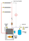
All closed-loop hydronic radiant heating systems require an expansion tank to accommodate the increases in volume of the heated fluid.
The classic method of sizing an expansion tank determines the volume of the system’s fluid when the system is at its highest temperature relative to its volume when cold. The expansion tank volume is then calculated to accept the change in fluid volume without letting system pressure climb to the point that the pressure relief valve opens.
The "Classic"
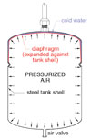
Here is a quick review of the classic sizing procedure for a diaphragm-type expansion tank in any type of closed-loop hydronic heating system:Step 1: Estimate the system’s fluid volume (not including any assumed expansion tank). Use the table inFigure 1to estimate the volume contained in the system piping.
You also need to look up the fluid volume contained in the system’s heat source. Most boiler manufacturers provide this data in their technical literature.
Add the tubing/piping volume to that of the heat source and any other miscellaneous system components (buffer tank, heat exchangers, etc.) and call the total estimated system volume Vs.
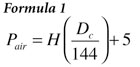
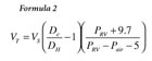
Step 2: Use Formula 1 to determine the required air-side pressure required in the expansion tank to ensure the diaphragm is fully expanded against the tank shell when the fluid in the system is cold (as shown in Figure 2).
where:
Pair = the proper air side pressure (before adding water to the system) (psi)
H = the height of liquid in the system above the inlet to the expansion tank (feet)
Dc = the density of the system fluid at its initial (cold) fill temperature (lb/cubic foot)
5 = an allowance for 5 psi static pressure at top of system to ensure that air vents at the top of the system can operate properly
The number 5 at the end of Formula 1 allows for 5 psi of static pressure desired at the top of the piping system. This helps push air out through vents, as well as to suppress vapor pocket formation in high-temperature systems.
The value “H” in Formula 1 is the vertical distance from the inlet of the expansion tank to the top of the piping system (see Figure 3). The greater this height is, the greater the static pressure on the tank, and thus, the higher the air-side pressurization required to ensure the diaphragm remains fully expanded when the system is filled.
Adjust the air pressure in the diaphragm to the calculated value before you add fluid to the system. This ensures that the diaphragm will not be partially compressed when the system is filled, reducing the acceptance volume of the tank when it’s needed (e.g., when the fluid starts to heat up).
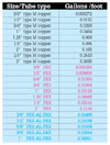
Where:
Vt = the required minimum volume of the expansion tank (gallons)
Vs = the system volume (gallons)
PRV = the pressure at which the pressure relief valve opens (psi)
Pair = the correct air side pressure (psi)
DH = the density of the system fluid at its final (hot) temperature (lb / cubic ft.)
Dc = the density of the system fluid at its initial (cold) fill temperature (lb / cubic ft.)
The volume of the system (Vs) was found in Step 1. The air side pressurization (Pair) was found in step 2, as was the density of the fluid when the system will be filled (Dc). The pressure relief valve setting (PRV) on most residential and light commercial systems is 30 psi.
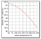
All that’s left is to look up the density of the fluid when the system is at maximum temperature. For water, use the graph shown in Figure 4. For antifreeze solution, look up the density in the manufacturer’s literature for the concentration being used.
Overly Conservative
This procedure sizes the expansion tank so the maximum system pressure is 5 psi lower than the relief valve setting, assumingallthe system fluid reaches the maximum temperature at the same time, presumably under design load conditions.But with a little thought, you’ll realize this scenario is not possible. The water temperature must drop in any system that’s delivering heat to a load. Thus, the assumption of all water in the system reaching the same maximum temperature simultaneously is not possible.
Now think about a large radiant floor heating system. Assume the water leaving the boiler is 180°F at design load conditions. Some of this water mixes with much cooler water returning from the floor circuits to produce a mixed supply temperature of 110°F.
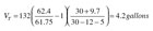
Imagine a facility with a 300,000 Btu/hr radiant panel system having a conventional boiler with a volume of 35 gallons, some near boiler piping with a volume of 4.5 gallons, and 9,500 feet of 5/8" PEX tubing in the floor slab. At design load, the water in the boiler and near boiler piping reaches 180°F, but the water in the radiant panel circuit only reaches 110°F. The volume in the floor circuits is approximately 132 gallons. That’s 77% of the total system volume. Assume the calculated air side pressurization of the expansion tank is 12 psi, and the system has a 30 psi relief valve.


For the fluid volume that reaches 180ºF, the minimum expansion tank volume is:
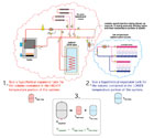
The above concept is illustrated in Figure 5.
Even the modified sizing procedure is conservative because it ignores the temperature drop of the fluid in the floor circuits and near boiler piping when the system is operating. This temperature drop tends to lower the average fluid temperature and, hence, reduce to total expansion volume.
Although there is nothing technically wrong with oversizing expansion tanks, it certainly adds to system cost. You could take a similar view when sizing piping, deciding on tube spacing in a heated floor, or selecting the size of electrical conductors. Good designers evaluate the alternatives using accurate procedures, then make an informed decision.


