Issue: 2/04
This article is a follow up to the article, "Selecting Fire Pumps for ESFR Sprinkler Applications," published in PME in March 2002. The original article outlined the design challenges associated with widely fluctuating residual and static pressures experienced in ESFR sprinkler systems. The article further offered a number of ways to remedy this problem by applying alternative fire pump system designs.
In brief, the problem amounts to the need to design fire protection systems for the worst case scenario. This philosophy requires that we design to deliver the minimum required pressure under residual, full-flow conditions. As such, the pressure at low flow or static conditions is a great deal higher. This is due to fact that pumps produce a higher pressure under low flow conditions, and due to the additional pressure available from the city supply main under static conditions. The situation can be further complicated in diesel applications by engine droop, the tendency for under-loaded diesel engines to run at a higher speed. The result is a system where the static pressure exceeds the pressure rating of the fittings. A number of potential solutions were presented, including the use of break tanks, relief valves, reducing valves, and pumps with "flatter" performance curves.
What was not mentioned in the article was another potential solution to the over-pressurization problem. At the time, it would have sounded far-fetched to even suggest using mechanical or electrical means to change the operating speed of the pump. Today, it is a reality.
NFPA 20 2003
NFPA Technical Committees are sometimes criticized for being resistant to change. This was not the case with the Technical Committee on Fire Pumps in the 2003 revision cycle. Right from the initial meeting at the end of 2000, the technical committee was willing to embrace new ideas. It was refreshing to see a group with many members who compete commercially on a daily basis put aside commercial interests to embrace change. What the committee accomplished as far as change was concerned was "unprecedented" in the words of Chairman John Jensen. The committee was faced with the challenge of resolving some of the recurring controversial issues such as main relief valve and limited service controller application. In addition to these discussions, the committee was charged with evaluating close to 200 public and committee proposals, and to incorporate the Standards Council's Manual of Style requirements. The result is a document that looks almost nothing like NFPA 20 1999.
Of the extensive changes, probably the most unusual change is the acceptance of application of devices capable of reducing the speed of a pump to prevent over-pressurization in a fire protection system. This new text has spawned a Task Group whose purpose is to define changes to the NFPA 20 standard to provide technical requirements for electric motor and engine speed controls. The Task Group has been helped immensely by experts outside the group. Key contributors both inside and outside the task group include Russ Anderson (Metron), Dana Haagensen (NFPA 20 staff liaison), John Kovacik, (UL task group chairman), Tim Killion (Peerless Pump Co.), Tim Lueck (UL), Steve Mezsick (Eli Lilly), Gayle Pennel (Schirmer Engineering), Ken Wauligman (Clarke Fire Protection Products), John Whitney (Clarke Fire Protection Products), and the authors.
Why Variable Speed?
The major driver behind the acceptance of this new means of pressure control is respect for the philosophy of the NFPA. NFPA standards are intended to define a minimum standard for fire protection, not to prohibit application of new technology that could reduce the cost of a fire protection system without diminishing its reliability. It is important to remember that almost all breakthroughs in the fire protection industry are born as products or services not allowed for in existing NFPA standards.
The principle behind varying the operating speed of a pump to limit pressure is not new. Reduced output pressure of a pump at reduced operating speed is well understood and is a consequence of the pump affinity laws. The pump affinity laws define how a centrifugal pump will perform at varying impeller trim and operating speed. The basic relations are as follows:
Q proportional to N
P proportional to N2
E proportional to N3
where:
Q = flow
P = pressure
E = hydraulic work
N = speed
The major implication for fire protection of the affinity laws is the pressure relation. Since this is a squared relation, a relatively small reduction in speed can result in a relatively large reduction in pressure. For example, a pump developing 150 psi of pressure at 1,780 rpm will develop 121 psi at 1,600 rpm.
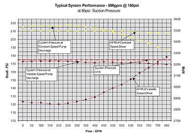
This looks good on paper, but does it work in reality? Figure 1 shows actual test data for a diesel driven pump operating under variable speed conditions. In this particular example, the design residual pressure for the system is 160 psi. The design has been done such that the fire protection system pressure rating is 175 psi. The design residual suction pressure available is 40 psi. If the static suction pressure in reality is 85 psi, it is clear (looking at the top performance curve) that the system pressure rating is exceeded by a constant speed pump running under no-flow conditions.
The lower performance curve shows the same pump running at reduced speeds. The lower speed curve indicates that even with a 45 psi supply pressure variation, the driver (designed for 3,560 rpm) only needs to reduce its speed to 2,850 rpm to maintain adequate pressure without exceeding the system pressure rating.
How Is the Speed Controlled?
There is a multitude of means of varying driver speed. Variable speed has been used for years in many critical duty applications, and in fact, is not new to fire pump applications. For decades, the City of New York has been applying variable speed technology for manual fire pumps in high-rise buildings. In this application, a manual controller that includes a manual drum switch and resistor banks is used to vary the speed of a wound rotor motor in discrete steps. This is done by varying the resistance in the rotor circuit of the motor to obtain some speed control of the fire pump. These controllers are supplied with anywhere from three steps to seven steps of speed control that must be manually set after starting the motor at full speed. Though there are a number of other means of controlling driver speed, we will limit this article to technologies applied for listed products or those products currently in UL or FM registration testing.Diesel drivers are inherently variable speed devices. The speed is determined by the amount of fuel delivered to the engine. In existing approved "constant speed" fire pump engines, the speed is set to a constant (varying less than 10% across the full range of engine load) by setting a governor on the engine throttle. Changing the throttle position will change the speed of the engine, and hence the speed of the pump. A series of engines is currently in the approval process using a purely mechanical speed control device to control or limit system pressure automatically by adjusting the engine speed to match a previously set pressure limit value. The product is expected to be available early in 2004.
The challenge of varying the speed of NEMA Design B motors is one that has been solved by the invention of the insulated gate bipolar transistor (IGBT), the heart of adjustable frequency drives (AFDs, also known as VFDs). NEMA Design B motors operate at speeds proportional to the frequency of the AC power applied at the motor terminals. As such, to get a motor to run at different speeds, a device that varies the motor input frequency is needed. Such a device requires semiconductors capable of interrupting and engaging high currents at high switching speeds. The IGBT fits the bill and has been applied for over 20 years in motor control applications where the speed of a motor needs to be varied.
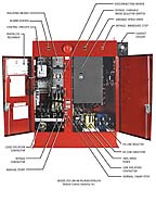
The principle of applying AFDs in a fire protection application is to have the pump run as it normally would at constant speed until such time as the pressure (as measured by a pressure transducer) reaches the upper limit. Once this pressure is reached, the proportional-integral-derivative (PID) controller in the AFD reduces the frequency of the power applied to the motor to prevent the pump from over-pressurizing the system. An added benefit of applying the AFD is that it provides soft-starting of the fire pump. Soft-starting reduces the inrush current of the motor, and reduces hydraulic shocks in the system caused by starting and stopping of the fire pump. A UL-listed product from Master Controls is on the market already and was displayed at the 2003 NFPA Exhibition in Dallas. The product fully realizes the benefits of AFD application by soft-starting and soft-stopping the motor, eliminating water hammer in addition to limiting pressure in the system.
When Does Variable Speed Make Sense?
The same principles apply in using variable speed on a fire pump as would apply to any device being designed into a fire protection system. The device should be used to reduce the cost and improve the reliability of the overall system. Variable speed should be considered for fire pumps where static pressures result in high system pressure ratings. A driver equipped with a variable speed pressure limiting control device can be used to eliminate high pressure fittings and reducing valves on zones in the system.
Though it is not permitted by NFPA 20, relief valves are being used as a means of pressure regulation in fire protection systems across North America. This is a result of a number of factors:
- 1) A lack of understanding of what constitutes good design practice;
2) Misinterpretation of NFPA 20;
3) Cost of alternative solutions;
4) The assumption that there are no design alternatives.
The latter three reasons for misapplication of the relief valve have been rectified in NFPA 20 2003 by acceptance of variable speed pressure limiting control. The first reason for misapplication of the relief valve can only be resolved by education and acceptance of NFPA 20 2003 at a local level.
As a side note, installation of pressure reducing valves on the zones of the sprinkler system is still allowed per NFPA 13 2003, section 8.15.1.2.
Application Considerations
To better understand when variable speed pressure limiting control should be applied in a fire protection system design, it is helpful to look at a few specific situations.1) ESFR Systems
Due to the higher pressure requirements and 175 psi design limit for ESFR sprinkler systems, variable speed can be employed to eliminate over-pressurization problems. The elimination of the main relief valve as an over-pressure protection device returns the relief valve to its intended purpose--system protection. Further, the device reduces the owner's maintenance costs for the life of the system by preventing thousands of gallons of water being dumped down the drain during weekly testing.
2) High-Rise Systems
Zoned high-rise standpipe systems are another opportunity for application. Whether the zones are serviced by parallel pumps, or series pumps, pump shutoff head can reduce the number of floors a pump can service without over-pressurizing the system. This can reduce the amount of floors serviceable by the fire protection system by as much as three of four floors. Applying variable speed could allow the system to service the extra floors, dramatically increasing the owner's available commercial space without increasing the cost of the fire protection system. Further, due to the limitation of pressure fluctuations, some of the reducing valves can be eliminated on branch piping and in the hose cabinets.
3) Long Runs of Pipe
Many new and existing industrial plants, warehouses, and "big box" retail outlets have long runs of pipe to service the sprinklers. These installations augment the over-pressurization problem. The additional system resistance caused by higher friction losses compounds the pump shutoff head and supply pressure variation problems. Reducing the high static pressures historically has been done by increasing the size of piping servicing the fire protection system.
Larger pipe sizes reduce the friction head, and hence the pump boost pressure. Pipe sizing need not be increased if a variable speed pressure limiting control device is applied on the fire pump, since one can design for higher pressure drops without the concern for over-pressurization.
Conclusion
Never before have designers had as much flexibility in fire pump system design. Though design flexibility is a positive thing for the industry, the same flexibility can lead to errors in application of products and design of installations. As with the relief valve, variable speed presents a potential for misapplication. It is recommended that experts be consulted when applying these new products. Of critical importance is that a relief valve still be installed when using a variable speed pressure limiting control device. This is to account for manual starting of the pump or failure of the variable speed device. Provisions for testing variable speed pressure limiting control devices (engaged or bypassed) have not yet been made in NFPA 20; however, the committee plans on addressing this problem in the next revision cycle of the code.Finally, when applying variable speed technology, the system design pressure, system maximum pressure and the speed control set points must all be carefully coordinated in addition to the other system design considerations. Further, the devices should not be used to design extra "safety factor" pressure into the system. Over-design not only increases driver sizing and cost, but can cause the system resistance curve to intersect the pump curve further to the right, resulting in run-out operation at reduced speeds. Engine speed control must be coordinated with the pump and system characteristics. Electric motor speed control requires the use of suitable motors and ratings. Either method requires careful attention to system and driver time constants for stable and reliable operation of the pumping system as is the case for any variable speed application.


