Issue: 10/02
If you design low-temperature hydronic systems, you've probably specified mixing devices to reduce the water temperature supplied by a conventional boiler to that needed by a low-temperature distribution system. Several options are now available for this purpose. In low-temperature radiant heating and snowmelting applications, the two most common are 4-way motorized mixing valves and variable speed injection pumping.
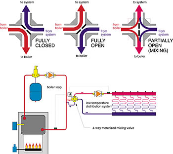
It's helpful to think of the mixing device as a "bridge" connecting the boiler loop to the distribution system. As such, the mixing device controls all heat flow into the distribution system. Figure 1 shows how four different devices can be configured to act as this bridge. (Note: Figure 1 could not be reproduced online. Please see print edition for reference.)
Most designers consider the primary function of a mixing device to be regulation of the water temperature on the supply side of the distribution system. This is an important function, but in many systems it's not the only function of the mixing device. In systems using "conventional" boilers, the mixing device must also ensure that boiler inlet temperature remains high enough to prevent sustained flue gas condensation.
4-Way Mixing Basics
The "classic" mixing device for connecting a conventional boiler to a low-temperature distribution system is a 4-way motorized mixing valve. A cutaway and application schematic of this valve is shown inFigure 2.The interior design of a 4-way mixing valve is rather simple. A vane attached to the valve shaft is rotated by the valve's actuating motor. The vane's position determines the proportions of hot and cool fluid entering the valve. Some of the entering hot water mixes with cooler water returning from the distribution system to establish the supply temperature. The rest of the hot water mixes with the remaining cool water, and the blend is routed back to the boiler. The objective is to establish the proper supply temperature, while simultaneously boosting the boiler inlet temperature high enough to prevent flue gas condensation. The latter function can only be accomplished when the controller operating the valve senses and reacts to the boiler inlet temperature. If this temperature is below an established minimum, the controller must reduce the flow rate of hot water entering the valve. This prevents the distribution system from absorbing heat faster than the boiler can generate that heat.
In some systems, the boiler loop circulator can be eliminated when the 4-way mixing valve is located close to a boiler having low flow resistance and low flow rate requirements while firing. In such cases, the momentum of the fluid in the distribution system, as it interacts with the vane in the mixing valve, will maintain adequate flow through the boiler. However, if the 4-way valve is one of several loads supplied by a common boiler loop, it should be piped to that loop using a pair of closely spaced tees, as shown in Figure 2. This eliminates interference between the low temperature distribution circulator and other circulators that may be operating.
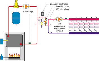
Variable Speed Injection Basics
A typical variable speed injection mixing system is shown inFigure 3.The faster the injection pump runs, the faster hot water is injected into the distribution system, the warmer it gets, and the greater its heat output.
As with 4-way mixing valves, the controller operating the injection pump must also sense boiler inlet temperature to protect the boiler from condensing mode operation. When the inlet temperature is below the set minimum, the speed of the injection pump is reduced.
For optimum performance, a variable speed injection system must be flow balanced so the injection pump operates at or close to full speed under design load conditions. This allows the controller to operate the injection pump over its full range of speed.
The Similarities
Modern 4-way motorized mixing valves and variable speed injection systems have much in common. They both can:
- Provide full P.I.D. control of the water temperature supplied to the distribution system.
- Provide full or partial outdoor reset of the supply water temperature based on outdoor temperature.
- Protect conventional boilers from condensing mode operation.
- "Exercise" the pump(s) and mixing valve during the non-heating season to prevent seizing.
From the standpoint of temperature accuracy, both provide virtually identical performance.
The Differences
Imagine two hydronic radiant floor heating systems that are identical other than their mixing devices. One uses a 4-way motorized mixing valve; the other uses variable speed injection mixing. Each uses a conventional boiler to supply the low-temperature load, and thus requires protection against sustained flue gas condensation.
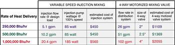
The table shown in Figure 4 compares estimated hardware costs of these mixing options for system outputs ranging from 250,000 to 1,000,000 Btu/hr. These costs are based on estimated trade (to the contractor) quotations obtained from wholesalers in early 2002. They include pipe flanges where needed on larger mixing valves and quality circuit balancing valves for the injection systems. They do not include ancillary hardware such as isolation valves, or short lengths of piping and fittings. They also do not include installation labor. The costs were averaged on some components when available from different manufacturers.
Beyond First Cost
When evaluating options for mechanical systems, it's certainly prudent to compare operating costs as well as hardware and installation cost.Injection pumps obviously require electrical energy to operate--substantially more electrical energy than does a comparable 4-way motorized valve system. Actuators used for the latter typically have small 24 VAC synchronous motors that operate on three-wire "floating" control signals of very short duration. Electrical power consumption is negligible.
There's also an operating cost associated with the head loss of each mixing system. Anytime fluid flows through a hydronic system component, some amount of head energy is dissipated. This head was provided by the circulator, which in turn used electrical energy to produce it.
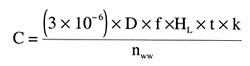
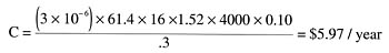
The cost associated with head loss can be estimated by converting the head loss back to an electrical input based on an assumed wire-to-water pump efficiency. Formula 1 can be used for this estimate.
Where:
C = operating cost ($)
D = density of fluid (lb/ft3)
f = flow rate (gpm)
HL = head loss (feet)
t = operating time (hours)
k = electrical energy cost ($/kwhr)
nww = wire-to-water pump efficiency (decimal percent)
A Moving Target
The operating cost of both mixing options was estimated for a system supplying a design load of 500,000 Btu/hr to a low-temperature floor heating system. The boiler water temperature was assumed fixed at 190 degrees F. The supply temperature to the distribution system at design load was 110 degrees F. The return temperature at design load was 90 degrees F. The circulator in the distribution system was assumed to operate continuously whenever outdoor temperature was below 65 degrees F. The wire-to-water efficiency of this circulator was estimated to be 40%.The injection mixing system only requires a small, wet-rotor 1/25 horsepower injection pump. Because this pump runs at different speeds and therefore different power levels throughout the season, estimating its total seasonal electrical usage is not a simple matter. The power usage depends on the load, which in turn depends on outdoor temperature. Pump affinity laws also state that pump power is proportional to the cube of the impeller speed. Hence, small changes in pump speed can yield significant changes in power consumption.
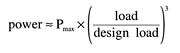
One pump affinity law states that flow is proportional to pump speed. For the systems being modeled, injection flow rate (for a fixed injection temperature) is approximately proportional to load. Therefore, injection pump speed is approximately proportional to load. Combining this with an affinity law stating that pump power is proportional to the cube of pump speed yields the following model for pump power based on load (see Formula 2).
Where:
Power = power input to injection pump at current heating load (watts)
Pmax = power input to injection pump at design heating load (watts)
Load = current heating load (Btu/hr)
Design load = design heating load (Btu/hr)
To see the impact of the pump power affinity law, assume the load is 50% of design load. Formula 2 calculates the power input of the injection pump at this condition to be 0.125 x Pmax, (e.g. 12.5% of design load power input).
A spreadsheet was developed to simulate the electrical usage of the injection pump over a full heating season. The load was calculated using "bin" temperature data for Syracuse, NY. The injection pump selected for the 500,000 Btu/hr system requires 85 watts of electrical input at full speed, which, in a correctly balanced injection system would only occur as design load conditions (0 degrees F). Based on these assumptions, the simulated seasonal electrical usage of the injection pump was 70.5 kilowatt-hours. At $0.10/kwhr, the seasonal operating cost of the injection pump is about $7.05 per season.
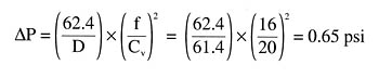
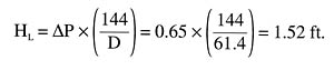
Head Loss = Cost
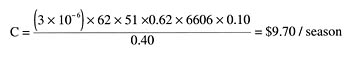
A 2.5" size 4-way mixing valve with a Cv of 100 was selected as the alternative to injection mixing in the 500,000 Btu/hr system. At a system flow rate of 51 gpm, the head loss of this valve is approximately 0.62 feet. Assuming flow through the valve whenever the outdoor temperature is at or below 65 degrees F (6606 hours in Syracuse), a wire-to-water circulator efficiency of 40%, and $0.10/kwhr electricity, the operating cost was estimated usingFormula 1and is shown in the accompanying equation.Before you conclude that injection mixing always has a lower operating cost than an equivalent 4-way motorized mixing valve, consider what happens in systems where the boiler is operated by an outdoor reset control. Under partial load conditions, the lower boiler temperature forces the injection pump to run at higher speeds. This increases electrical energy consumption, but by how much?
The spreadsheet was modified to simulate a system in which the boiler is reset from a design load temperature of 190 degrees F, down to a minimum supply temperature of 140 degrees F. The minimum supply temperature occurs when outdoor temperatures are 30 degrees F or above. At temperatures below 30 degrees F, the injection pump would theoretically run at full speed (85 watts) based on the principle of proportional reset. Above 30 degrees F, power consumption decreases as the supply temperature requirement drops. For the Syracuse location, this all works out to an estimated seasonal usage of 253 kilowatt-hours of electrical input. The seasonal operating cost is now $25.30 based on $0.10/kwhr electricity. This is a substantial increase in electrical usage relative to the injection system supplied by a fixed temperature (190 degrees F) boiler.
Although the operating cost of the injection pump is now higher than that of the 4-way valve, it still is a very small percentage of the total seasonal operating cost of a 500,000 Btu/hr system. The fuel savings attained by operating the boiler(s) with reset control would significantly overshadow the higher operating cost of the injection pump in a system of this size.
Both injection pump scenarios are conservative in that neither accounts for internal heat gain or temperature setbacks, both of which would reduce injection pump duty.
Summary
Both 4-way motorized mixing valves and variable speed injection mixing can accurately control water temperature in the distribution system. Both can also protect a conventional boiler when paired with a low-temperature distribution system.The operating cost of the 4-way valve may be higher or lower than that of the variable speed injection pump depending on the operating conditions. The estimated operating cost of either option is a small percentage of the overall operating cost of a large system.
Based on current hardware prices, the injection system holds a definite first cost advantage over the 4-way valve system. This cost advantage increases as the heating capacity of the system increases.
The piping associated with a large 4-way valve, especially those using flanged connections, will result in higher installation (labor) costs relative to those of a comparable injection system.
There will be some systems using conventional boilers in which a 4-way valve will not require a pumped boiler loop. This can not be done with injection mixing.
The eventual availability of very small/low-cost pumps developed specifically for injection mixing applications could further lower operating cost, especially in smaller systems.
For optimum performance, a variable speed injection system must be flow balanced so the injection pump operates at or close to full speed under design load conditions. This balancing is not necessary with a 4-way mixing valve.
The use of variable speed injection mixing has been steadily increasing in North America in recent years. However, the 4-way motorized valve remains the benchmark mixing method in the much larger European hydronics market.
The bottom line: Both mixing options have their strengths and weaknesses. When sized and installed properly, either can provide the vital link necessary to deliver unsurpassed comfort in radiant heating applications. Take your pick.
