
A couple of years ago, I was asked for input on a proposed heating system in which two electric boilers were being added to a school’s heating system. These new electric boilers would supplement the output of the existing gas-fired cast-iron boiler, and take advantage of low “off-peak” electrical rates.
The load was four zones of low water temperature floor heating. Great! Lower water temperatures allow most heat sources to operate at higher efficiency. However, this is not the case for electric boilers. For them, 1 kWh of electrical input yields 1 kWh of thermal output regardless of water temperature.
The designer planned to operate the gas-fired boiler at temperatures high enough to avoid sustained flue gas condensation and to install a “bypass circulator” as another means of boosting boiler inlet temperature.
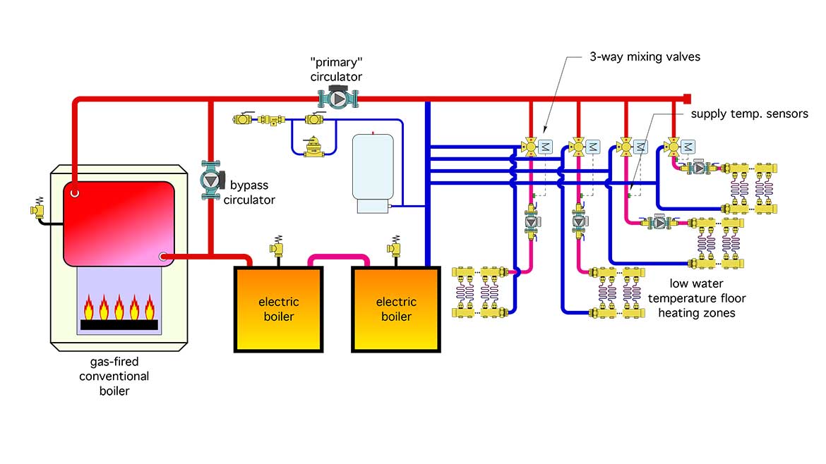
A 3-way motorized mixing valve would be used to reduce the supply water temperature in each of the four zones. The proposed conceptual schematic for the modified system is shown in Figure 1.
FIGURE 1
The punch list
I’ve had hundreds of opportunities to review proposed system schematics. Each one of them is a “Where’s Waldo?” challenge.
I don’t begin with the assumption that every schematic is totally messed up. Just because a designer might choose to use different hardware than I would, or put that hardware together using a different — but valid — piping topology, doesn’t mean there’s something wrong. Instead, I look to see if the fundamental (“Hydronics 101”) details are present. Those details include (in no particular order of priority):
- Providing the necessary operating conditions for the proposed heat sources;
- If multiple heat sources are present, how are they connected;
- Provision(s) for hydraulic separation of circulators;
- Means of controlling differential pressure when valve-based zoning is used;
- Means for balancing flow through branch circuits;
- Are the headers sized for relatively slow flow velocity (2 ft/sec max);
- The ability to isolate major components for service or replacement;
- The location at which the expansion tank connects to the system relative to circulators;
- Purging provisions for all portions of the system;
- Provisions for air and dirt separation;
- Appropriate pipe and circulator sizes;
- Location of temperature sensors;
- How the control system will operate;
- Provisions for preventing thermal migration;
- Provisions to prevent inadvertent flow (forward or backward) in circuits that are supposed to be off while other circuits are operating;
- Counterflow through all heat exchangers; and
- Provisions to limit or prevent forward or reverse thermosiphoning from thermal storage tanks.
With all these in mind, let’s look at the issues present in Figure 1.
Seriously flawed
One detail that immediately jumps off the page is the series piping of the electric boilers. Never pipe boilers, or other hydronic heat sources in series. There is no upside, just multiple downsides, such as not being able to remove one boiler for service without temporarily changing the piping to keep the system operating. Or, in the case of mod/con boilers or heat pumps, lowering the efficiency of the downstream heat sources due to higher inlet water temperature. Flow of heated water through inactive boiler(s) also needlessly increases jacket and stack heat loss.
With very few exceptions it’s best to connect multiple heat sources in parallel. This allows for independent operation, accommodates differences in required flow rates and provides the ability to isolate or remove any of the heat sources if ever necessary without shutting down the remainder of the system.
Don’t overcook it
Although it’s possible to operate the system shown in Figure 1 at higher water temperatures and mix down to achieve the necessary supply temperatures for the floor heating circuits, it isn’t necessary. This is especially true for electric boilers that don’t create flue gases that could condense. The gas-fired boiler can be protected against sustained flue gas condensation by installing a 3-way mixing valve that senses and reacts to the boiler inlet temperature. This valve attempts to keep the boiler inlet temperature at or above 130° F whenever possible. The bypass circulator shown in Figure 1 cannot react to boiler inlet temperature and as such cannot provide consistent anti-condensation protection.
Checks and balances
There are no check valves shown within the individual zone circuits. This would allow some amount of flow reversal through inactive zones.
Lose the bubbles
No purging valves or central air separators are shown in Figure 1. It would take a lot of aggravating hours to fill and purge this system as shown.
Sensorship
Supply water temperature sensors for mixing devices should be installed downstream of the associated circulator whenever possible. This helps ensure complete mixing of the hot and cold streams prior to passing by the sensor that is controlling the mixing device.
The Makeover
Figure 2 shows one approach that eliminates these issues. Keep in mind that this is not the only possible way to eliminate the problems present in Figure 1, but it does organize the hardware into a consistent and repeatable arrangement, one that’s likely to reduce or simplify the amount of hardware and piping needed.
FIGURE 2
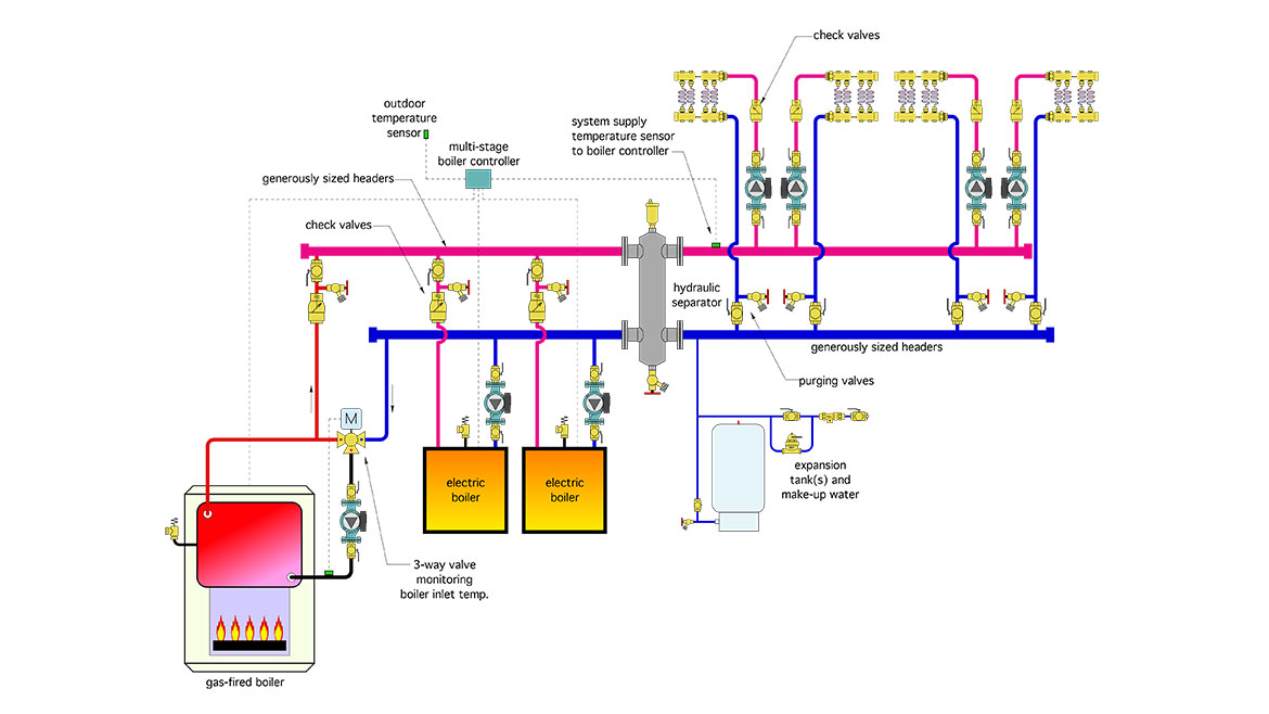
All three heat sources are piped in parallel, and trimmed so that any one of them could potentially be removed for service if necessary, without affecting the operation of the remaining heat sources. Each boiler has its own circulator that runs only when that boiler is active. Each boiler also has a check valve and purging valves. These allow each boiler to be isolated, purged and protected against reverse flow when one boiler is off and the others are on.
The gas-fired boiler, which is now protected from low inlet water temperatures by a 3-way mixing valve that responds to boiler inlet temperature. When that temperature is less than 130° F, the cold port of the mixing valve is fully closed. This routes the water leaving the boiler directly back into the boiler. Very little heat is released to the headers. This allows the boiler to quickly warm above conditions that cause sustained flue gas condensation.
All three heat sources connect through generously-sized headers to a hydraulic separator. In addition to isolating the pressure dynamics of the heat source circulators from those of the load circulators, the hydraulic separator provide efficient air and dirt separation for the system.
The water temperature on the load side outlet of the hydraulic separator is monitored by a 3-stage heat source controller, which operates all three heat sources based on its settings. Those settings would be based on the delivered price of heat from gas as well as electricity, especially when the latter is available on low “off-peak” rates. Regardless of the fuel mix, the heat source controller’s responsibility is to ensure that an adequate supply water temperature is available whenever one or more of the loads is active. That supply water temperature would typically be based on outdoor reset control.
The 3-way mixing valves can be eliminated. They are not needed. All mixing occurs within the hydraulic separator. This significantly reduces cost and complexity.
Finally, each of the four zone circuits is equipped with a check valve and purging valves.
A final observation
Although the makeover shown in Figure 2 is viable, the use of electric boilers to supply a low-temperature load leaves a major potential improvement on the table (e.g., using air to water heat pumps rather than electric boilers). The supply water temperature range required by the floor heating system would allow such heat pumps to operate at relatively high COPs. As such, they could deliver the required heat to the load using much less electrical energy input (i.e. if air-to-water heat pumps with a seasonal COP of 2.7 were used they would only consume about 37% of the electrical energy required by the electric boilers).
As my friend and colleague Robert Bean would point out, the use of electric resistance heating in situations where heat pumps can do the job well is a big waste of EXERGY. The future of HVAC is not just about low energy use. It also requires recognition of thermodynamically sound methods of providing that energy. As an industry, we need to move away from dissipating high-grade/high-temperature energy into low-grade heat. Heat pumps supplied by renewably-sourced electricity are moving the industry in that direction.

