
Every year, manufacturers develop new or improved products for the North American hydronic market. Product development planning by those manufacturers depends on several factors. Here are a few of the main considerations:
- Is there an opportunity in the market that is not being met?
- How would the product sell against competing products?
- How many competitors are already offering a similar product and at what price?
- How will the product be sold through existing distribution channels?
- Can the product be made with existing tooling and staffing?
- What profit margin would the product generate?
- What’s necessary to package and ship the product?
- What are the technical support needs of the product? and
- Will the product “steal” sales from an existing product offered by the same company?
These considerations are not in any order of importance. Any one of them could be the “driver” that determines if a new product will be developed, or filed away as a non-starter.
A designer’s prospective
Hydronic system designers, who are generally not constrained to any one manufacturer, have thousands of products to choose from. Their job is to assemble components that meet the technical requirements of the system (e.g., capacity and comfort), provide efficient, long-lasting and reliable operation, provide value that justifies the cost, allows easy servicing and maintains a trusted and lasting relationship with the client.
While pursuing the above, designers might conceive an idea for a device that isn’t currently available. Some might think that their flash of inspiration, if disclosed, should be immediately put into mass production by at least one manufacturer. Perhaps they envision patents leading to years of lucrative royalties, as hundreds of thousands of devices, based on their idea, flow into the market. Although very few entrepreneurs might be so fortunate, many more fail to consider their concept from the manufacturer’s point of view.
If the product concept doesn’t fill a recurring need across as wide a swatch of the industry as possible, if it can’t be manufactured and sold at a profit, if it’s impractical to package or ship, or if it falls short any of the manufacturer’s consideration listed above, it’s very unlikely to make it to production.
I’ll give it a try
So, after the above “reality checks” regarding new product offerings, I’ll dare to offer “propositions” for devices that I think address needs and offer opportunities for manufacturers. I’ll attempt to justify the need for these products in terms of added value, improved performance, elimination of problems and future relevancy.
1. Anti-condensation insulation shells for circulators: The rapidly growing market for hydronic-based heat pumps (e.g., air-to-water, and water-to-water) requires circulators to handle fluids at temperatures well below the dewpoint of surrounding air. Residential and light commercial hydronic systems using heat pumps typically rely on wet-rotor circulators with cast-iron volutes. The shape of those volutes, flanges and associated isolation valves makes it difficult to properly insulate them such that surrounding air can’t reach their surfaces. Without proper insulation, the surface of the volute will oxidize within a few weeks of conveying chilled water. Figure 1 shows two examples of this surface oxidation.
Figure 1A
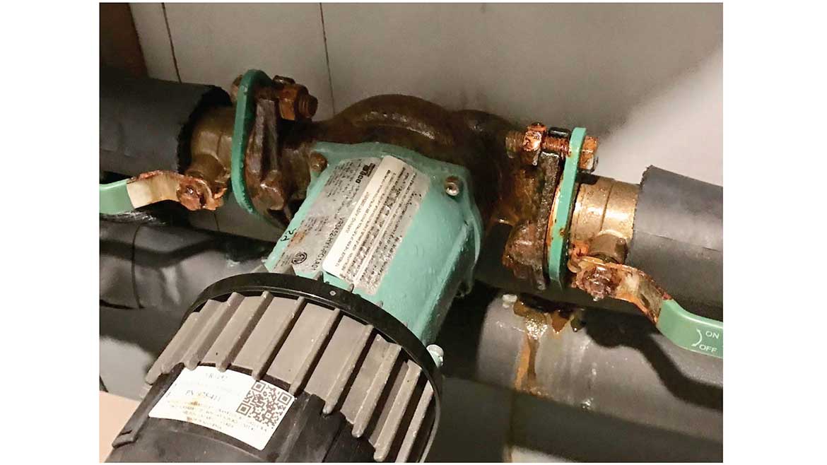
Figure 1B
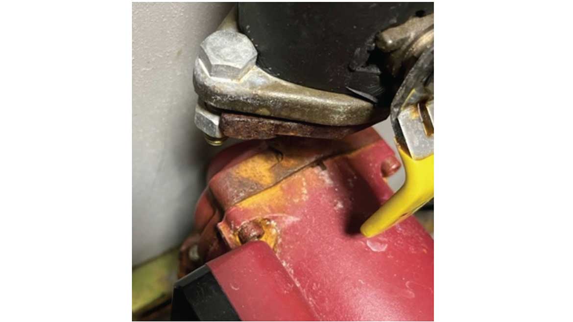
I can assure you that this surface oxidation is not limited to any specific brand. I’ve observed it on several different makes and models of circulators conveying chilled fluid.
Some circulator manufacturers currently offer form-fitting rigid foam insulation shells for certain model circulators. Those shells snap together over the volute. All seams on the shell must then be sealed to prevent surrounding air from migrating toward the volute.
So what’s the problem? Two issues remain:
- The availability of insulation shells is currently very limited relative to the number of wet-rotor circulators that could potentially be used in chilled fluid applications. More shells are needed for more models; and
- The insulation shell, while adequate to protect the circulator’s volute, does not protect the flanges or isolation valves connected to the circulator. The zinc-plated steel used for the flange bolts and handles on isolation valves eventually corrodes — take a close look at Figure 1 to see this.
Ideally, circulator manufacturers — or perhaps other manufacturers that recognize the opportunity — would offer circulator insulation kits, consisting of volute shells with accompanying isolation flanges. These kits would provide uninterrupted coverage of the circulator volute, flanges and isolation valves. Readily available pipe insulation would butt up to the insulation kit on both sides of the circulator. The kit would be installed after the circulator is mounted and piped, sealable at all seams. Ideally, it would allow for easy removal and reinstallation without major damage to the insulation.
2. 3-position diverter valves: Another product need that dovetails with the increasing use of hydronic heat pumps is a 3-way / 3-position diverter valve. It would be used for two common installation situations: Where two or more hydronic heat pumps, each independently controlled, need to be connected to a 4-pipe header systems (e.g., heated water supply & return, and chilled water supply & return) or when a two pipe fancoil or air handler needs to be connected to a 4-pipe distribution system.
Examples of these situations are shown in Figures 2 and 3.
Figure 2
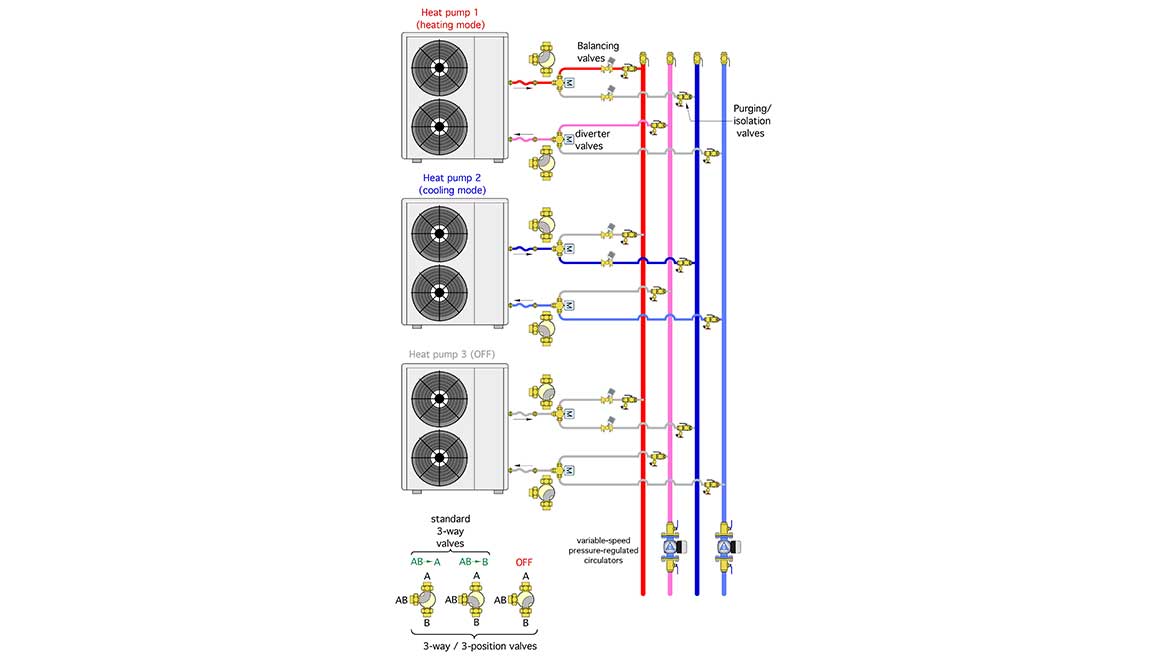
Figure 3
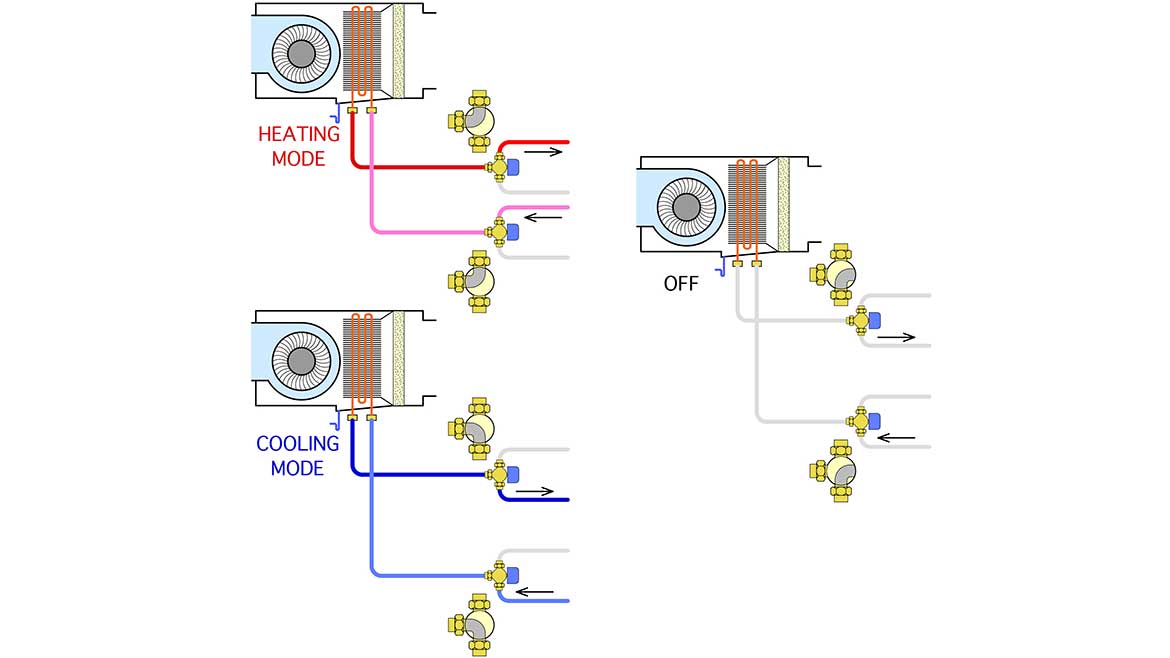
A 3-way / 3-position diverter valve replaces the need for the 2-way valve motorized ball valve and thus reduces complexity and cost.
3. Indirect water heaters for heat pumps: Many installation drawings for heat pump systems show a diverter valve that directs heated water from the heat pump to either space heating or domestic water heating. Figure 4 shows a typical configuration.
Figure 4
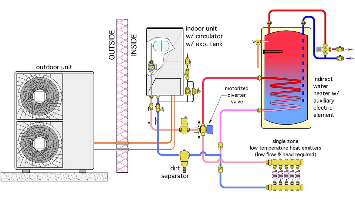
o maintain reasonable COPs, current-generation heat pumps need to operate at temperatures no higher than 130° F. Even lower temperatures are preferred when possible.
Most currently available indirect water heaters were designed for use with boilers. Their DHW production rates are typically listed for coil inlet temperatures of 180° and 200° F. Those temperatures are far above what most current-generation heat pumps can supply. The internal heat exchanger coils in many current-generation indirect tanks will not be able to transfer the rate of heat supplied from the heat pump while operating at inlet water temperatures of 130° F or less. This can cause short-cycling of heat pumps controlled as on/off devices, and ultimately shorten their service life.
The market needs indirects with significantly larger internal coils to be compatible with the supply water temperatures available from heat pumps. Several European manufacturers have tanks with large internal coils, but the pickings are pretty slim in the current North American market. As an encouragement to manufacturers, these “higher performance” indirects would also improve the efficiency of mod/con boilers during DHW mode. They would also improve the performance of solar thermal collectors, and allow for wide temperature swings in thermal storage tanks heated by biomass boilers, off-peak electricity or combined heat and power systems.
Until such tanks are available, and alternative is to use a generously sized brazed plates heat exchanger with a circulator as shown in Figure 5.
Figure 5
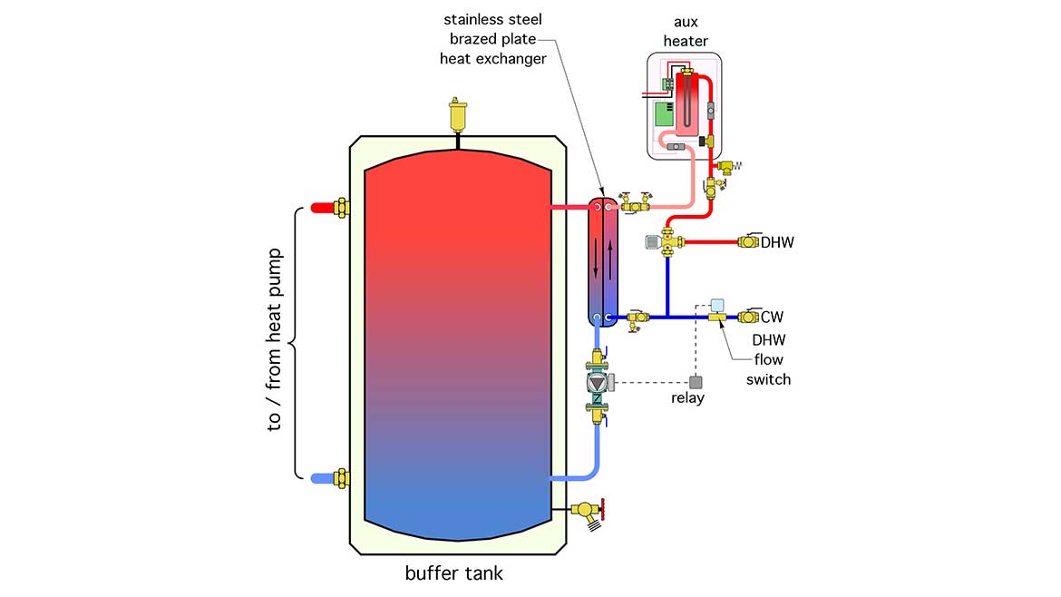
When the flow switch detects a flow of domestic hot water the circulator routes heated water from the upper portion of the buffer tank through the primary side of the heat exchanger, as cold domestic water passes, in counterflow, through the secondary side. The domestic water temperature leaving the heat exchanger depends on the buffer tank temperature. With proper sizing, a heat exchanger can be selected such that the leaving domestic water temperature is within 5° F of the temperature at the top of the buffer tank. In some systems, an auxiliary water heating device may be needed depending on the temperature maintained in the buffer tank.
4. Injection mixing with ECM circulators: Before mod/con boilers were the norm, many hydronic systems included hardware to mix higher-temperature water from a conventional boiler with return water from the distribution system to achieve a suitable supply water temperature.
One of the common mixing methods used in North America was variable speed injection mixing. Several manufacturers developed controllers that modified the electrical waveform supplied to the permanent split capacitor (PSC) motors used on small wet rotor circulators. Today there are likely tens of thousands of systems in operation with this type of mixing control. Most are working fine, but, like most components, will eventually reach a point where the controller or circulator will fail and require replacement
So what’s the problem? A quick check on what all circulator manufacturers are offering as their current generation products reveals a pending predicament. All circulator manufacturers are moving away from PSC motors toward circulators with EC (Electronically Controlled) motors. Five years from now, it’s doubtful if circulators with PSC motors will be available through normal sales channels. The injection mixing controllers used for PSC-based circulators are not compatible with ECM-based circulators.
The industry needs a controller that can operate a circulator with an EC motor, and thus serve as a drop-in replacement for an existing injection mixing assembly. Without this, a significant portion of the system’s piping will eventually have to be changed to accommodate a mixing valve to replace the injection mixing assembly.
Several ECM-based circulators have the ability to accept a speed control signal. Analog control signals of 2-10 VDC or 4-20 ma are common. Some circulator manufacturers also have circulators that can accept a digital speed control signal. Given the electronics already present in most modern ECM-based circulators, expanding the control platform to accept inputs from temperature sensors should be possible, and may offer a solution in which no external controller is needed. All the necessary control logic would be programmed into the circulator.
Variable speed circulators with temperature sensing ability can also be used for anti-condensation protection of boilers, and capacity control for chilled beams or chilled water coils in air handlers. It’s mostly a matter of having the necessary algorithms within the firmware inside the circulator. It’s a good opportunity that spans from the replacement market to many types of contemporary HVAC applications.
5. Hydronic heat pumps with “system sensor” capabilities: Many of the currently available air-to-water and water-to-water heat pumps with variable speed compressors have internal temperature sensors that measure the leaving water temperature and use it to adjust compressor speed to maintain a target outlet temperature. This is fine when the heat pump connects directly to the load. In that case, the water temperature leaving the heat pump is essentially the same as the water temperature reaching the heat emitters.
In other systems, where there’s a buffer tank or hydraulic separator between the heat pump and the heat emitters, the water temperature supplied to the heat emitters could be significantly lower than that leaving the heat pump. Figure 6 shows an examples of a system where this scenario can occur.
Figure 6
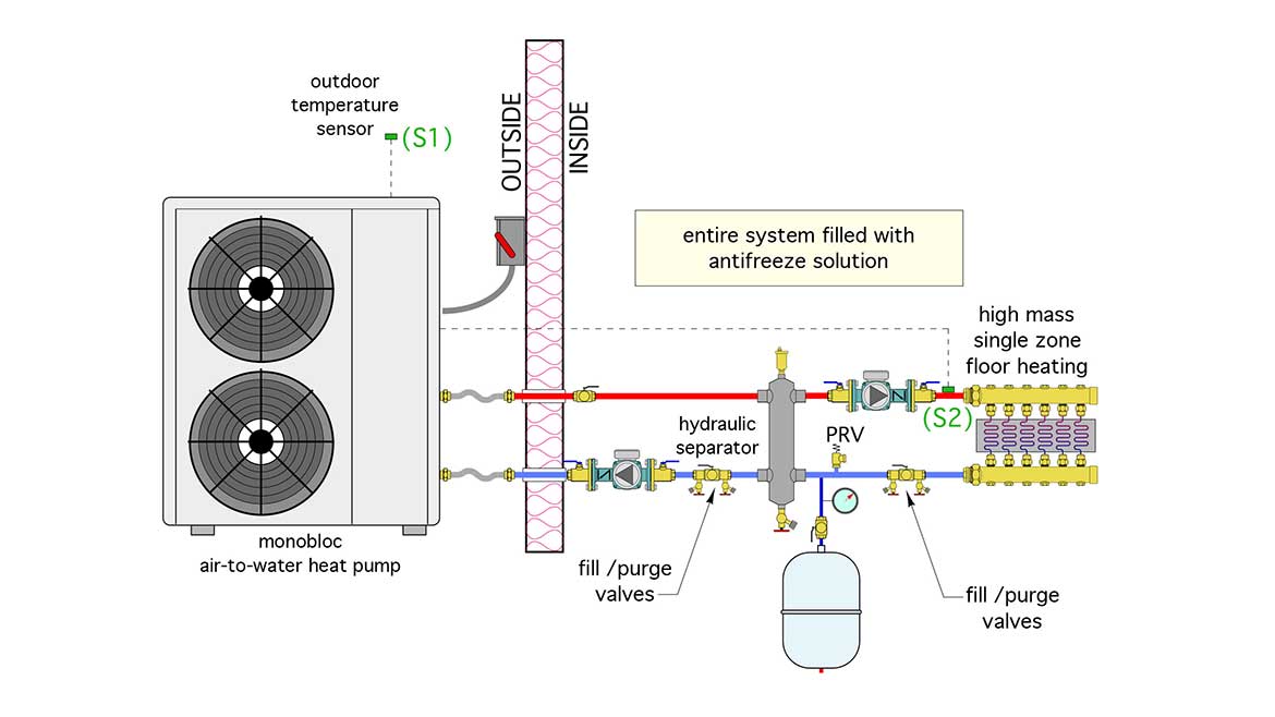
The reduction in supply water temperature happens when the flow rate to the distribution system is higher than the flow rate through the heat pump. Mixing occurs at the point of hydronic separation (e.g., within a buffer tank or hydraulic separator).
The solution to this scenario is a sensor mounted on downstream of the hydronic separator, or within a well on a buffer tank. The heat pump’s compressor speed is then based on the temperature reported from this “system sensor” rather than the heat pump’s internal sensor.
Early generation mod/con boilers created the same scenario (e.g., they weren’t capable of regulating heat output based on the true supply water temperature to the heat emitters in systems with buffer tanks or other forms of hydraulic separation. That has changed. Several mod/con boiler offerings can now monitor a “system sensor” rather their own boiler outlet temperature sensor. Suppliers of air-to-water and water-to-water heat pumps need to evolve their internal controls to do likewise.
Go for it
In closing, I welcome feedback from readers or manufacturers regarding the “propositions” described above. I have no patents or other intellectual property rights on any of this, and encourage any entrepreneur to consider what has been discussed. In my opinion, products that provide solutions to these challenges would be welcome additions to the North American hydronics market.


