Siphonic drainage, introduced to Europe in the 1960s, is an engineered rainwater drainage system that utilizes the natural power of a siphon to drain the water from elevated surfaces (roofs, decks, etc).
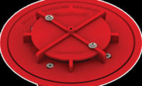
The system is comprised of a drain, which is designed to inhibit the naturally occurring vortex and an especially configured network of pipe and fittings designed to flow full of water under negative pressure conditions. Pipework can be routed in a building with no pitch or slope, for long horizontal distances, before dropping to low level at a loca-tion to suit the designer, allowing it to be easily coordinated with other services.
The roof drains must comply with ASME A112.6.9 and piping materials and configurations must comply with ASPE/ANSI 45-2018.
There are many potential benefits of using siphonic drainage, and the earlier it is introduced in the design process, the more benefits can be achieved. Ponding levels on the roof can be greatly reduced by utilizing the highly efficient siphonic roof drains available.
Points to consider for gravity configuration
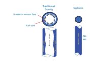
Conventional roof drains have no recognized test data available at this time. Therefore, ponding levels are there-fore difficult to determine at design flow rate;
Pipework from the roof drains drops directly down a stack to large, low-level collection pipes, installed at a pitch, either externally or under the building floor, requiring extensive excavation and backfill; and
The pitch in the pipework can be restrictive, and if long distances are involved below ground, the discharge could end up being lower than the receiving pond or main storm sewer.
Points to consider for siphonic configuration
Siphonic roof drains undergo extensive testing and report specific flow data per ASME A112.6.9, allowing the plumbing designer to accurately determine ponding levels;
The roof drains are collected by high level manifolds that can be routed within the building, allowing for easier coordination of the pipework with other services;
The siphonic pipework drops at a preferred location, allowing greater flexibility; and
Siphonic pipework is self-cleaning, as it is restricted to having the minimum flow at 3 feet per second at all times during design flow.
How does siphonic drainage work?
Siphonic drainage operates using an engineered pipework system and an especially developed roof drain that prohibits the induction of air into the system. The absence of air is essential for generating negative pressure.
It’s important to note that a siphonic system does not require priming or charging with a head of water in order to operate. The progression from a conventional drainage system to a siphonic drainage system is swift and seamless, with the system draining water throughout the process.
Main stages
There are four main stages of progression from a conventional drainage system to siphonic operation:
Wavy flow — This is the operation of the system during light rain or melting snow, where the water flows into the drain below the level of the baffle plate, and the water can flow through the pipework with no back-up or restriction in flow.
Plug flow — As the Storm increases in intensity, flows in the pipework increase and begin to be restricted and back-up, forming plugs of water that completely fill the pipework. When these plugs reach the top of the stack, they accelerate downwards, leaving pockets of negative pressure. At roof level, the water level increases up to the underside of the baffle plate, and air is excluded from the system.
Bubble flow — As the storm intensity increases, air is purged, and as the negative pressure and velocities increase, only periodical bubbles of air can enter the system along with water. The system is effectively at full design flows.
Full-bore flow — All air is purged from the system. The baffle is fully submerged and the system has reached its design rate.
If there is not enough rainfall to generate siphonic action, the system will act as a conventional system. Flow patterns will increase and decrease along with the changes in rainfall intensity.
Design parameters
Various design parameters are present to ensure each siphonic system performs correctly and within safe limits. Any system that complies fully with the design parameters will perform as intended to provide dependable protection for the building on which it is installed.
System calculations
Each siphonic system is designed to the specific roof/building that it serves. There are several factors that affect siphonic system design, including location, roof type and piping materials. The design begins with placing the roof drains in the low points of the roof/gutter. The designer then calculates the flow rate for each roof drain.
Traditionally, systems were calculated manually using a complex series of hydraulic calculations. This is a long process and involved a vast number of trial and error calculations. Today, these calculations are determined with the application of specifically designed software, providing greater accuracy and convenience.
These software packages are used to model the pipework, fittings and drains required.
Some software packages use “straight lines” to create the image of the pipework and fittings, but other recently developed packages use 3D models to construct systems that apply accurate material dimensions such as fitting radii, hub depths and cut-lengths of pipe. Installers can read the exported calculations as cut-sheets or prefab drawings, saving time on site.
Once the designer has completed the system, pipe lengths and diameters can be modified until a fully compliant set of results is achieved. Hydraulic data updates in real time with every change in design.
Some software packages offer additional features, including:
Theoretical versus design disposable head checks, applicable in surcharge situations;
Cavitation checks that ensure the system doesn’t include pressure/velocity conditions that are potentially damaging to piping materials; and
Online updates and collaboration facilities.
Additionally, exports available from the software package may include isometric details, 3D export compatible with commonly used design software, a summary of hydraulic calculations and bills of materials.
Siphonic drainage systems must be installed in accordance with the local codes and building regulations, as well as guidelines established by ASPE/ANSI 45-2018


