
With winter fast-approaching, it’s a good time to consider the significant role drains have on sprinkler systems.
I’m not talking about drains installed in floors for the control of spillage, but rather the importance tool drains serve in testing your sprinkler system’s performance and reliability.
For those of you who have systems subjected to freezing, is your system prepared for this season’s cold front? NFPA 25: Standard for the Inspection Testing and Maintenance of Water-Based Fire Protection Systems, provides requirements for three types of drains. Section 3.3.10.1 of the 2017 edition of NFPA 25 defines the term “main drain” as the primary drain connection located on the system riser. A “sectional drain” is defined in the next section as a drain located beyond a sectional control valve that drains only to a portion of the system. NFPA 14: Standard for the Installation of Standpipe and Hose Systems, defines an “auxiliary drain” as a drain connection installed to permit draining water from a trapped section of pipe.
The purpose of drains on fire-sprinkler systems is to drain the system to facilitate system maintenance, and in the event of a fire, drain the system to replace the sprinklers that activated. When systems are taken out of service, properly sized and arranged drains assist in minimizing the amount of time a system is out of service.
The purpose of a main drain is to provide a test connection to verify water-supply valves are open and to reveal any changes in the condition of the water supply by comparing results to those of previous tests. This means a main drain test is required as part of the system-acceptance testing. This establishes baseline data for the water supply against which future tests can be compared.
A common misconception is that a main drain test connection is a sufficient means for conducting a flow test. In accordance with NFPA 13: Standard for the Installation of Sprinkler Systems, main drain connections generally are not sufficient for conducting the flow test because main drains have not been sized to accommodate system flow.
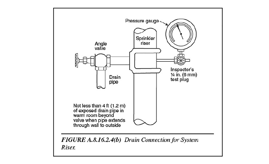
Figure A.8.16.2.4(b) of NFPA 13. In accordance with Section 13.2.5 of NFPA 25, a main drain test is required to be conducted annually for each water supply lead-in to a building water-based fire-protection system.
Main drains are installed on system risers to drain water from the overhead piping after the system is shut down to allow for work to be performed on the system. See Figure A.8.16.2.4(b) of NFPA 13 above.
In accordance with Section 13.2.5 of NFPA 25, a main drain test is required to be conducted annually for each water supply lead-in to a building water-based fire-protection system.
The next five steps outline how to conduct this test:
-
Record the pressure indicated by the supply water gauge;
-
Close the alarm control valve on alarm valves;
-
Fully open the main drain valve;
-
After the flow has stabilized, record the residual (flowing) pressure indicated by the water supply gauge; and
-
Slowly close the main drain valve.
By recording available static and residual pressure during each test, a database can be created and used for tracking the relative condition of the water supply during the life of the system.
A decrease in the static or residual pressure (or both) could indicate a deteriorating water supply, an obstructed supply pipe or a partially closed valve. In accordance with NFPA 25, the official rule states when there is a 10% reduction in full-flow pressure when compared to the original acceptance test or previously performed test, the cause of the reduction is required to be identified and corrected, if necessary.
Also, it should be noted how long it takes for the system pressure to return to normal. Excessive time may be an indication of a partially closed water-supply control valve.
Moving on
As a general rule of thumb, the piping network in traditional wet-pipe systems is permitted to be installed level. Since these systems are installed in areas not subjected to freezing conditions, the small amount of water that may not drain from the piping is not considered a problem. However, the piping installed for dry pipe and preaction systems is required to be pitched at specific slopes depending on whether or not the system is installed in refrigerated/non-refrigerated areas.
For trapped sections of pipe
Auxiliary drains are provided to drain the water. Auxiliary drains differ depending on the type of system and capacity of the trapped section of the system. For traditional wet-pipe systems and preaction systems in areas not subject to freezing, auxiliary drains are required where the capacity of isolated trapped sections of pipe is 5 gal. (18.9 L) or more, and need to be piped to an accessible location. For dry-pipe systems and preaction systems subject to freezing, an auxiliary drain, also known as “drum drip” or “drip leg,” is required and needs to be accessible in order to be drained quickly.
How does water get into a dry pipe or preaction system?
Water can enter these types of systems when the dry pipe valve is tripped or from moisture condensation from the pressurized air in the system.
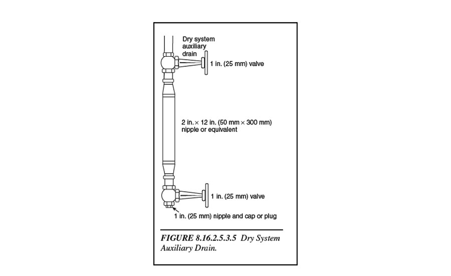
This type of auxiliary drain will consist of two 1-in. valves and one 2-in. x 12-in. condensate nipple or equivalent, accessibly located in accordance with Figure 8.16.2.5.3.5 of NFPA 13: Standard for the Installation of Sprinkler Systems.
It is important to mention NFPA 13 does not restrict the number or location of auxiliary drains. However, the more auxiliary drains are installed, the more likely it is one will be missed when the dry-pipe system is drained. For this reason, NFPA 13 requires an information sign on the sprinkler system riser indicating where any auxiliary drains are located.
NFPA 25 requires auxiliary drains in preaction systems to be operated after each system operation and before the onset of freezing conditions (and thereafter as needed). It is good practice to establish a program for monitoring the condition of the system and the operation of the auxiliary drains.
The next five steps outline how to conduct this test:
-
Close the upper valve to prevent tripping the dry-pipe system;
-
Open the lower valve until all water/condensation has drained;
-
Close the lower valve;
-
Reopen the upper valve; and
-
Repeat steps 1-4 until no observable water/condensate drains from the lower valve.
The frequency may be decreased to weekly or longer intervals depending on the volume discharged. When preparing for cold weather, the auxiliary drains should be operated daily with the frequency of operation decreasing depending on the discharge of accumulated water.
Winter is coming and good communication between owners and service providers regarding system maintenance can make a significant impact on a system’s reliability and performance.
For additional information, please visit www.nfpa.org/13 or www.nfpa.org/25.

