Solar Design Notebook: Where should the heat exchanger be placed in a drainback solar water heating system?
|
|
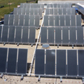
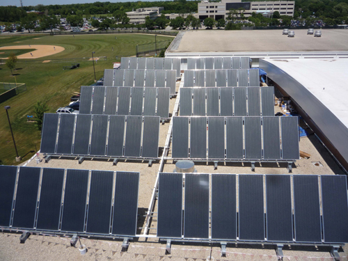
Drainback systems don’t require a “heat dump,” especially one that can function without utility-supplied electricity to protect against stagnation conditions. Eliminating a heat dump lowers cost and simplifies installation. Photo courtesy of Solar Service Inc. |
I’m a big fan of solar thermal systems that use drainback freeze protection. I like them because of the issues they eliminate, many of which are associated with the alternative of using a glycol-based antifreeze in the solar collection circuit. Here is a list of those issues.
The absorber plate in a typical flat plate collector can approach 350ºF if stagnation occurs on a warm and sunny afternoon. Such temperatures will degrade glycol-based antifreeze, turning it into an acid that can corrode the absorber plate as well as other components in the system.
In contrast, the collectors in a drainback system do not have any fluid in them during stagnation and should “ride out” stagnation without any damage. In fact, all collectors that meet the OG-100 certification by the Solar Rating and Certification Corp., a requirement for most government tax credits, must pass a 30-day dry stagnation test.
|
|
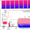
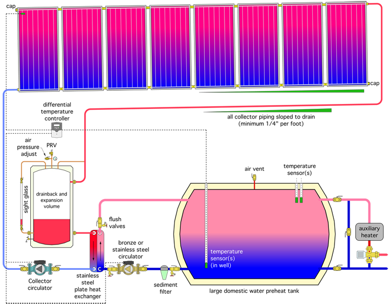
Figure 1 |
Downstream thinking
One of the best applications of solar thermal systems is domestic water heating. Facilities such as laundries, restaurants, nursing homes, hospitals and correctional institutions often have consistent high demands for domestic hot water and thus are excellent candidates for solar water heating.
The system shown in Figure 1 is one approach that merges the benefits of drainback freeze protection and the need for commercial- and institutional-scale domestic water heating.
This system uses four port “harp-style” collectors. To ensure complete drainage, the collector array requires a minimum side slope of 1/4 in. per ft. All piping in the collector circuit should also be sloped for drainage.
Whenever the collector temperature rises a few degrees above the temperature near the bottom of the storage tank, the collector circulator and tank circulator are turned on by the differential temperature controller. Water is lifted up through the collector supply piping and collector array. In a properly designed system, the flow velocity at the high point of the collector array will be at least 2 ft. per second. This allows the water to entrain air and carry it back down to the top of the drainback tank.
Within a short time after the start of a collection cycle, a siphon forms in the collector return piping. This eliminates most of the initial lift head present at the very beginning of the cycle. Modern differential temperature controllers take advantage of this by reducing the speed of the collector circulator based on the significantly reduced head loss of the now-filled collector circuit. This reduces the power consumption of the collector circulator during the remainder of the cycle.
After passing through the drainback tank, the water heated by the collectors passes through the primary side of a flat plate heat exchanger. Cool domestic water from the lower portion of the thermal storage tank flows through the secondary side of the heat exchange and carries the absorbed heat back to the thermal storage tank.
The water temperature in the thermal storage tank will vary over a wide range depending on weather conditions. Following one or two sunny and warm days, the water temperature may be well above the required delivery water temperature. On less productive days, the water may only get preheated to 80ºF or 90ºF and thus will require a boost from the auxiliary heater before passing to the load.
Unless otherwise provided for in the plumbing system, an ASSE 1017-rated thermostatic mixing valve should always be installed at the beginning of the plumbing distribution system to ensure safe domestic hot water delivery temperature.
|
|
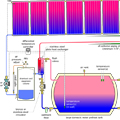
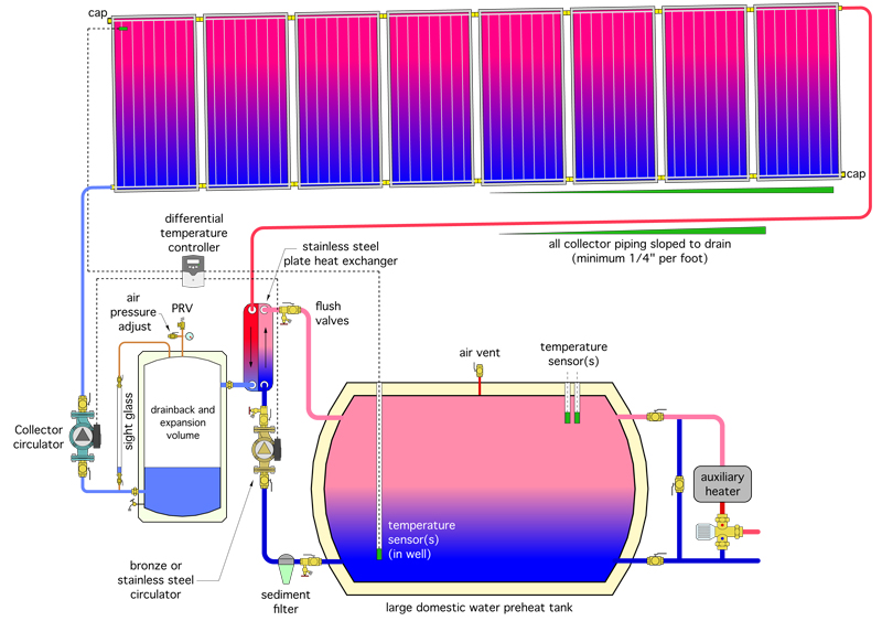
Figure 2. |
Room for improvement?
Although the system represented by Figure 1 has been successfully used in many applications, it has one characteristic that I still question: Standby heat loss from the drainback tank. The inside surfaces of the drainback tank, whether in contact with hot water or hot air and vapor above the water, will be heated during the collection cycle. This provides a driving force for heat loss through the insulated jacket of the drainback tank and into the mechanical room. The hotter the inside of the drainback tank the greater the rate of heat loss.
Any design modification that could keep the inside of the drainback tank cooler during the collection cycle would reduce this heat loss. This leads to the question: Why not locate the heat exchanger upstream of the drainback tank?
Figure 2 shows a schematic based on this proposed modification. The hot water returning from the collector array passes through the heat exchanger first and then flows on to the drainback tank.
This “upstream heat exchanger” allows the inside of the drainback tank to be cooler during the collection cycle. However, it also means that water in the primary side of the heat exchanger must drain out at the end of each collection cycle. My question is: Does repeated filling and drainage of the primary side of heat exchanger create any problems?
Earlier this year, I posed this question to several manufacturers of stainless-steel flat plate and brazed plate heat exchangers. I told them to assume the solar collector circuit is a closed loop that recirculates the same “clean” water each time it operates. The air and water in this circuit are “captive” as they would be in any closed-loop hydronic system.
I got responses from several manufacturers. Although none of them had tested their products in this configuration, the consensus seemed to be that it would not present problems provided the following is recognized:
1. The drainback time will be increased because air in the drainback tank will have to “percolate” back through the relatively narrow passages inside the heat exchanger at the end of the collection cycle.
2. The heat exchanger should be installed vertically as shown in both figures to expedite air removal at the start of each collection cycle.
3. The minimum flow velocity through the heat exchanger should be 0.2 ft. per second to ensure turbulent flow that enhances heat transfer.
I don’t see a slowing of the drainback process due to the presence of the heat exchanger as an issue. My justification comes from having observed drainback systems containing float-type flow meters in the collector supply piping. During drainback, the float immediately drops into the narrowest portion of the flowmeter body and all drainage has to pass through the annulus between the float and the tapered body. This would appear to offer significantly more resistance to drainback than the combined internal passages through a flat plate heat exchanger.
I definitely concur with mounting the heat exchanger in a vertical orientation to assist with air removal.
Finally, given that the minimum recommended flow velocity in the piping coming back from the collector array is 2.0 ft. per second - 10 times the required minimum for turbulent flow in the heat exchanger - point No. 3 should not be a problem.
So far so good, but I’ve still not tested this concept, nor am I familiar with any systems that have used it. That being said, I’ll throw it out to pme readers for feedback.
If you think there are any unforeseen issues with locating the heat exchanger upstream of the drainback tank, as shown in Figure 2, feel free to drop me an email at the address below explaining what you think they are and why you think they will occur. Provide technical support for you opinions.
Also, if any reader is familiar with a system configured like this, please let me know how it’s working or if there have been issues associated with the upstream heat exchanger.
I’ll pass along any supported information or observations that I receive in a future Solar Design Notebook column.


