These last steps are crucial in completing the rainwater harvesting process. (Part 4 of this four-part series).
In my article in pme’s June issue, “Cistern Management for Rainwater Harvesting” (Part 3 of this series), I discussed the importance of cistern inlets, overflows, sizing and floating pump inlets. The central premise has always been that the overall health of a rainwater harvesting system starts with the cistern. The final installment here in my four-part series will discuss methods engineers can employ to design effective and cost-efficient final treatment components. With a good cistern design, final treatment is simple.
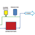
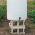
When transferring water into a building for final use as flushing water for toilets and urinals, one of the first important principles to understand is that an interior so-called “day” or “buffer” tank is necessary to provide storage and treatment (See Figure 1). Think of the exterior cistern as bulk storage and the interior tank as a treated, ready supply. Such a tank is typically sized to meet the water supply needs for a couple hours. An efficient size is about 500 to 750 gal., and such tanks constructed of polyethylene or fiberglass are readily available off the shelf (See Figure 2).
The buffer tank is central to a flushing water system and serves several purposes.
First, it provides a means of adding supplemental city water during dry periods by means of an air gap. Some jurisdictions may allow a hard-piped connection through an approved reduced-pressure zone backflow preventer, which can directly feed the flushing water system when rainwater is not available, but other jurisdictions may require an air gap.
Second, the tank allows for the collection of other water sources such as HVAC condensate and clear water waste streams such as reverse osmosis reject water. Most jurisdictions would not allow the comingling of rainwater with tap water sources of waste such as reverse osmosis water so it would not be possible to use the cistern, which overflows to the storm sewer, to collect tap water waste streams.
Third, the tank allows for the proper mixing and contact time of disinfectants before the water is distributed to the building fixtures.
As shown in Figure 1, rainwater is transferred from the cistern to the day tank. As discussed in Part 3, this transfer would be made by means of a small transfer pump coupled to a floating inlet. The transfer rate is typically between 20 to 30 gpm for most systems, which allows for a steady transfer of water to the tank for a fill time of 10 to 15 minutes. This transferred water passes through a set of fine filters, typically 5 microns, to remove any floating particulates that may be present.
Singing the blues
In some jurisdictions (Massachusetts, for example), rainwater used for flushing toilets and urinals in a building must be marked with a nontoxic blue dye to visually distinguish the water as nonpotable to protect against inadvertent cross connections. The other benefit of the coloration is to provide a more consistent aesthetic appearance to the water, which can sometimes have some coloration regardless of treatment level. The dye is typically best injected during tank filling. Having established a set 20- to 30-gpm fill rate, the dye can be injected proportionately with either a metering pump or an educator and achieve adequate mixing and a consistent level of coloration in the system.
Injecting “on demand” as the water is sent to the distribution system can be problematic as flow rates fluctuate dramatically. The buffer tank decouples the treatment from the fluctuations. Blue dye injection is not required in all jurisdictions, but it is considered advisable practice and is not expensive to maintain. Such nontoxic blue dye is common food coloring that can be purchased as a concentrate and mixed with water in a 35-gal. container. Of course, dye injection is not practical for all applications, such as cooling tower makeup, laundry and irrigation.

Disinfection and chlorine
Other than fine particulate filtration and possible dye coloration, the only other necessary treatment precaution is disinfection. In a small household system, disinfection by ultraviolet light may be adequate. However, in larger systems and in some jurisdictions a disinfection residual in the distribution piping system and in the buffer tank may be necessary. This involves the use of either chlorine or bromine, with chlorine being more commonly used. With the highly variable and fluctuating flows of a flushing water system, the buffer tank’s advantage to chlorine addition becomes obvious. However, the handling of chlorine has typically been a challenge in maintaining these systems.
The handling of chlorine solutions (liquid form) can pose difficulties. Exposure to the eyes or skin can be harmful. The off gassing of the chlorine in a room can lead to odors and corrosion of metal (i.e. electrical conduits, panels and pipes). Over time the chlorine solution breaks down and becomes ineffective. However, as any swimming pool owner knows, there are much easier methods of adding chlorine.
Many pools and whirlpool spas are equipped with in-line chlorine feeders using solid tablets or sticks (Figure 3). The same method is easily adapted to rainwater treatment. As shown in Figure 1, a small side stream taken from the discharge of the distribution pumps with a flow-regulating valve and solenoid valve can be used to place an in-line erosion feeder.
With the placement of a chlorine sensor (an oxidation-reduction potential sensor), the level of chlorine can be monitored and controlled. Maintenance is reduced to refilling the injector with chlorine tablets and replacement of the ORP sensor every two to three years. The level of free chlorine in the water is typically maintained between 1 to 2 ppm. Higher concentrations would tend to be corrosive to piping systems.
European engineers have used the equipment and design methods described in this four-part series for decades. The general wisdom coming from these techniques is “let nature take its course,” given favorable conditions such as removal of organic debris by first flush and inlet screening, development of biofilm in the cistern and oxygenation of the water.
Most importantly, it is too tempting to overdesign these systems and include complicated components that consume resources and energy to a point where the benefits of collecting rainwater diminish to nothing.
Read here for Part 1 (January 2012, pme).
Read here for Part 2 (March 2012, pme).
Read here for Part 3 (June 2012, pme).