Four Factors
Those familiar with dry pipe system designs know there are four basic factors that affect the design, installation and performance of dry pipe systems. These four principles are:
- Air and water supply pressures
- System capacity and piping configuration
- Size of test sprinkler
- Dry pipe valves
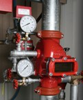
Air and Water Supply Pressures
A. System air pressure: The air pressure within dry system piping that keeps the dry valve closed and prevents water from entering the system. This is dictated by the static water supply pressure and the dry pipe valve design.
B. Static water pressure: The water supply pressure at the base of the riser with no flow into the sprinkler system. This pressure dictates the system air pressure required to keep the dry pipe valve closed.
C. Residual water pressure and flow: The water supply pressure at a given water flow rate. Each water supply follows a unique curve in which the pressure drops as the flow rate increases. This significantly impacts the time required after the dry valve trips for a steady discharge of water from the test connection to be established.
System Capacity and Piping Configuration
A. Capacity. Total volume of all piping on the system side of the dry pipe valve. Affects the amount of air that must be discharged from the system before steady water discharge is established at the test connection.
B. Piping configuration (tree, loop, grid):
I. Tree. Consists of dead-end branch lines, cross-mains and feed main. Only the feed main, cross-main and the one branch line with the test connection must have air displaced by water in order for water to reach the test connection. Air in the remainder of the system can be compressed into dead-end piping. This piping configuration produces the fastest water delivery times.
II. Loop. Has dead-end branch lines, but cross-mains are looped. Increases the amount of air that must be displaced by water in order for water to reach the test connection.
III. Grid. Currently not allowed in dry systems because the air in all branch lines and cross-mains must be displaced by water in order for water to reach the test connection, resulting in very long water delivery times.
Size of Test Sprinkler
The orifice size of the test sprinkler controls the rate at which air is discharged from the system piping. The rate of discharge and volume of air being discharged control the water delivery time after the dry pipe valve has been actuated.
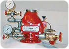
Dry Pipe Valves
Dry pipe valves have traditionally been designed as differential pressure valves. The clapper, which holds water out of the dry system, is designed with the surface area of the airside greater than the surface area of the water side. In this way, a lower air pressure can hold back a higher water pressure, thus reducing the volume of air in the dry system that must be discharged in order for water to reach the test connection.
Other designs of dry pipe valves include “low pressure latch type” that depend on actuators and a quick opening device to work together for the valve to function properly.

System Operation and Performance
To fully understand dry pipe system performance, we must look at the sequence of events that occur and the impact each has. When dry pipe sprinkler systems are ‘trip tested’ for acceptance, the following events occur after the inspectors test valve is opened:
1. Air pressure begins to drop in the system as a result of the open inspectors test valve. The loss of air pressure in the system causes the dry pipe valve to trip at its designed air/water ratio, or when an optional accelerator trips the valve on loss of air pressure.
2. When the valve trips, water begins to fill the system by compressing trapped air and forcing air from the inspector’s test connection.
3. Water reaches the test connection and a steady water discharge is established.
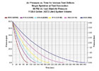
Low pressure latch clapper dry pipe valves operate by use of an additional device called an actuator. The actuator operates as a simple differential device, wherein loss of air pressure in the system at a greater rate than the threshold limit causes the actuator to move from its set position to an open position. This vents water from the diaphragm chamber of the main valve and releases the rod and latch that hold the clapper closed inside the main valve.
Since these actuators are designed for use with “low pressure dry pipe valves,” one can expect the air movement to be slow. This is obvious, as shown in Figure 1. The recommended air setting pressure of these systems varies with static water pressure and can be as low as 10 psi.
The performance of a 1,000-gallon system with a K5.6 inspectors test and a 100 psi static water supply was tested. A manufacturer-recommended 15 psi set pressure resulted in 76 seconds to achieve full (relief) flow. As with traditional dry pipe valves, latch clapper dry pipe valves will normally require the use of an accelerator to compensate for the slow activation time.
Use of An Accelerator
An accelerator shortens the time required to trip a dry pipe valve since they are very sensitive to pressure changes and significantly reduce the effect of system volume. Different models of accelerators offer different performance. Some typically trip a dry pipe valve in 4 to 10 seconds from the opening of the inspectors test valve. Other manufacturers publish times that range from 4.5 seconds to 25 seconds. The activation time is dependent on the system volume, system configuration and test orifice size.
The use of an accelerator can significantly reduce the trip time of a dry pipe valve, but has a negative impact on the water delivery time after the valve trips. The water delivery time is increased due to higher air pressure in the system when the valve trips since the accelerator will trip the valve before the air pressure in the system drops to the valve differential pressure.
The combined effect, though, of a properly operating accelerator is to reduce the overall time required to deliver water to the test connection. It is very important that we not lose sight of the fact that, by their very nature as sensitive devices, accelerators require a high level of testing and maintenance in order to operate dependably. Unfortunately, history shows us that they do not always receive the required level of attention.
Test Orifice Size
The size of the inspectors test orifice will not only affect the trip time as previously discussed, but will affect the water transit time. In order for water to fill the piping between the dry pipe valve and the test connection, it must displace air. The size of the test orifice determines the rate at which air leaves the system through the orifice.
Water Supply
While all water supplies are unique, they share one common trait for any given flow; there is a corresponding pressure. As flow increases, the pressure available decreases. For any given flow, the higher the pressure and the greater the flow, the faster the water will displace air and reach the inspectors test in a dry pipe system.
A weak water supply is resisted by air pressure in the system as well as lower flow rates that delay the transition time. Prior to dry pipe valve actuation, the system air pressure setting is dependent upon the static water supply pressure to the system and will vary by location.
The valve trip pressures for the water supplies shown in Figure 2 are 10.9, 14.6 and 18.2 psi, respective to the 60, 80 and 100 psi water supplies.
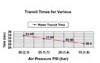
Air Pressure in System When Valve Trips
Air pressure in the system resists the fill rate of the water supply.Figure 3clearly shows the effect of air pressure in the system shown inFigure 4when the dry pipe valve trips, specifically when the test orifice is as small as K5.6. Figure 3 shows the effect of the air pressure in a given system.Piping arrangement plays an important role in the performance of water transition time.
When a dry pipe valve is equipped with an accelerator, the valve will trip faster. When the valve actuation time is decreased through the use of an accelerator, the residual air pressure in the system is much higher than would have been experienced had the air pressure been allowed to reach the normal trip ratio. The result is that when using a quick opening device on a dry valve, the incoming water front is subjected to more air pressure in the system at the instant the valve trips. Additional air pressure at the time of the valve trip will delay the water transition time.
Piping arrangement plays a significant role in water transition, as demonstrated in the examples here.Volume is not always the key indicator for transition times. Volume and piping configuration must be considered. These are variables that have never been previously addressed by any codes or design standards.
Compression
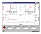
This refers to the time water first reaches the test outlet to the time when the water pressure is maintained above the minimum required. This is often referred to as “full flow” or “when the outlet stops spurting air.” This value is easier to establish by computer calculations than the judgment of three people standing at the test outlet debating the definition.The most definite description of full compression is the point or time at which the water volume entering the riser equals the water volume discharging from the sprinkler.This truly means that all of the trapped air is compressed and stable (no longer fluctuating). This value is not known in the field and can be identified by computer validation.
The more critical measure for adequate fire protection is the point at which the discharging sprinkler meets or exceeds its minimum flow or density requirement. A field test or delivery time calculation should end when the sprinkler is functioning at the minimum designed flow. Additional air escaping from the sprinkler is not significant as long as the discharge density is not disrupted.
Dry system performance will be greatly improved with the knowledge of actual water delivery times. Future performance-based designs can take advantage of actual water delivery in modeling versus the prescriptive volume time rules in older editions of NFPA.
References
1.Fire Protection Handbook, published by the National Fire Protection Association, Quincy, MA, and Society of Fire Protection Engineers, Bethesda, MD.
2.NFPA Standards, published by the National Fire Protection Association, Quincy, MA.
Sidebar: Computer Calculations for Dry Pipe System Performance
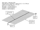
NFPA 132 (2002 edition) allows calculations to be submitted in lieu of a field validation test. And now, computer calculations are available for dry pipe system performance, thanks to a software program called SprinkFDT.The program’s dry pipe model is characterized by a system of straight pipes connected by nodes. Nodes can represent either a point of transition from one pipe size to another, elbows or bends, tees and laterals for dividing or mixing streams and valves, and exit nozzles such as an open sprinkler. The water supply can be modeled as either a static water supply or variable water supply, like a pump-driven water supply.
The dry pipe system modeled is the conventional tree-type system (i.e., single cross-main supplies water to branch lines that are fitted with automatic sprinklers). Each pipe/node in the model is categorized as a member of a feed main, cross-main, riser nipple, branch line and drop/sprig portion of the dry pipe system.
The SprinkFDT equations for flow properties of the gas and liquid are based on equations for unsteady fluid flow. These equations are used to solve for flow properties in the regions of fluid flow and gas flow in the system at any point in time, with the appropriate boundary and continuity conditions coupling the equations for water and gas. Additionally, the program models such phenomena as bubble flow and mixing between gas and liquid.