
Worldwide consumption of water is rising at double the population growth rate. Many municipalities are struggling with supplying water to meet the needs of desired growth. At the same time, federal stormwater regulations are causing municipalities to consider various options in order to reduce reliance on aging water and stormwater infrastructures. Decentralized rainwater harvesting systems collect and supply water on-site and reduce reliance on potable water supplies.
Decentralized rainwater harvesting systems can also have an impact on energy demands. Efforts to reduce our energy consumption have overlooked the cost of energy required to supply water to end users. Treating and distributing drinking water in the U.S. accounts for 4% of the total energy used. Almost 80 cents of every dollar spent by municipalities on water treatment and distribution is for electricity (Electrical Power Research Institute, 2002). Much of this potable water is used for non-potable water needs. An alternative to this energy-intensive process of supplying people with water is falling from the sky: rainwater.
Harvesting rainwater has a plethora of environmental, social and economic benefits. Why should you take a closer look at rainwater harvesting? The reasons are many:
- Save money on utility bills
- Manage stormwater runoff
- Reduce non-point source pollution
- Reduce reliance on aging infrastructures
- Attain points for LEED certification
- Recharge local aquifers with tank overflows
- Reduce detention pond collection requirements
- Increase building resale value
Did you know that one inch of rain on a 1,000-sq.-ft. roof is 623 gallons of water? Think of all this water flowing off the roof. Rather than becoming pollutant carrying stormwater, rainwater can be stored and re-used on-site - reducing the volume of stormwater reaching rivers and streams and supplying potable and non-potable needs in and around the building.
Non-potable uses of water include: Toilet flushing, irrigation, water features, laundry washing, vehicle washing, cooling towers, fire suppression, pool/pond filling and manufacturing processes.
When considering a rainwater harvesting system, local authorities should be consulted regarding regulations or codes pertaining to rainwater. The use of rainwater is fairly new to most localities. Others may have codes and regulations in place. Most municipalities appear focused on cross connections and air-gaps.
Rainwater systems can be applied to single-family and multi-family residential, commercial and industrial projects. When designing a system for new construction, incorporating a rainwater harvesting system can reduce or eliminate the requirements for detention ponds. Civil and plumbing engineers should work together during this process to accomplish their goals and meet regulatory requirements.
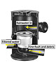
Diagram of a vortex filter.
As Easy As 1-2-3-4
When designing a rainwater harvesting system, four basic steps should be followed and implemented. While these steps will often be a part of the civil engineer’s design, the result will be a low-maintenance, high water quality system with reduced risk of failure, decreasing the need for additional treatment and concern from the plumbing designer.Systems should be designed to protect and enhance the naturally occurring biofilm in the tank. The biofilm is similar to biofilms used in water treatment, and it maintains water quality through the breakdown of organic matter and trapping metals (Coombes et al., 2006). If the four steps are followed (seeFigure 1), the tank will not require cleaning or emptying, which could destroy the healthy biofilm layer.
Step 1
A pre-filter should be used to remove debris washed from the roof surface during rainfall events. There are many variations of pre-filters available. For an effective system, the filter should not require maintenance after every rainfall event, and the first flush should be diverted away from the tank. When a rain event begins, the first water from the roof surface carries much of the debris.
Diverting this “first flush” away from the storage vessel helps maintain high water quality in the storage vessel. These devices are normally placed in the system after the gutters and before water enters the storage vessel. We have found the WISY filters to be a low maintenance and high performance first flush diverter and filter. A WISY filter will help oxygenate the filtered water before the water enters the storage vessel, preventing stagnation. The filter also separates debris from clean rainwater and protects water quality before storage. Maintenance of the WISY stainless steel filter insert is as simple as rinsing the filter with a hose or in a dishwasher.
Step 2
How water enters the storage vessel is very important. By using a smoothing inlet, sediment and biofilm on the bottom of the storage vessel will not be stirred. The smoothing inlet also helps to oxygenate the water and exchanges the old water with new pre-filtered water. New water enters the bottom of the vessel in an upward direction and forces the older water upward and out the overflow.
Step 3
How water is extracted from the storage vessel is equally important in supplying high quality water. Water extracted just below the surface is normally the highest quality. The use of a floating filter allows for the extraction just below the water surface. Water extracted from the surface or tank floor contains small particles and can cause problems with plumbing seals, seats, and valves.
Step 4
In order to maintain a healthy water system, some overflow should occur. The overflow will help remove fine floating debris through a surface skimming action. Protection from small vermin entering the storage vessel is needed to maintain water quality. The overflow is directed to the sewer or stormwater line, or day lighted to a pervious area like a bioswale and/or rain garden. The local municipality may have guidelines regarding where the overflow should be directed. If the overflow system is connected to sewer or stormwater lines, it may be necessary to protect the system from gases entering the storage vessel. This can be accomplished with a multifunction overflow device or proper P-Trap.
Storage tanks for rainwater come in many forms and sizes. These tanks are made of a variety of materials including polyethylene, fiberglass, concrete, steel and modular cells.

Diagram of floating filter.
Storage Vessels/Tanks: Selection and Design
Selecting the appropriate tank size can be one of the keys to a successful, efficient and cost-effective rainwater harvesting system. In larger commercial and educational facilities, it is often advantageous to utilize a multi-tank rainwater harvesting system. The larger tanks, which hold the collected rainwater, are typically outside and below grade.The smaller tank, often referred to as a "day tank," is placed inside the facility, generally in a mechanical room in proximity to the municipal water supply of the building. This "day tank" holds water, treated as needed for its end use, that has been pumped from the larger holding tanks. While the sizing of both tanks depends on the expected water demand, the thought process for sizing each tank is different. Once the correct tank sizes are selected, tank materials and specific locations can be determined.
While design of the large rainwater storage tank often falls to the civil engineer, cooperation between the plumbing engineer and the civil engineer is crucial. For a cost-effective design, this tank should be included in the stormwater management plan. However, sizing the tank requires more than a typical detention calculation.
Sizing a detention area is based on the roof area and a single event (for example, 5” of rainfall in one hour).

Figure 1. An illustration of a multi-tank system.
As long as the rainwater harvesting system will be backed up by municipal or well water, the rainwater system only needs to meet average demand, not the peak or maximum demand.
For example, in an office building with 60 offices, three conference rooms that each hold 20 people and a fitness center with a 15-person occupancy, the true expected demand is likely the water use of 60 people, not 135 people. Designing the rainwater harvesting system to meet the water demands of 135 people would result in an over-sized and more costly system.
Once this demand is determined, the best way to calculate the storage tank size is modeling the system using daily rainfall data. Daily water level in the tank can be calculated from input (rainfall x roof area x filter and runoff efficiency x 0.62) and the daily demand. A conversion factor of 0.62 is used to convert from square feet-inches to gallons.
In general, increasing the tank size leads to a greater ability to supply water because a larger tank can capture more rainwater in a large event. However, beyond a certain tank size (specific to each combination of rainfall, roof area and demand), increases in tank size only lead to marginal benefit. By modeling a variety of storage tank sizes, the designer can select a tank size that supplies a reasonable water supply, but is not over-sized.
The size of the "day tank" or treated water tank is similarly driven by the expected demand. However, the size of the treated water tank depends more on peak demand than average demand. Again, selecting a reasonable expected peak demand rather than a design load peak demand is important.
Consider, for example, a sports arena with a maximum occupancy of 3,400 people and a rainwater harvesting system supplying 30 water closets and eight urinals. While the overall water supply system needs to be sized for a design load peak demand, it is unlikely that all fixtures will be used simultaneously. A more reasonable high demand event might be one-third of the total occupancy going to the bathroom during half time.
A reasonable starting assumption would be that the crowd is half men and half women and 20% of the men use the water closet. Allowing a little over 1 minute per water closet use and 30 seconds per urinal use, this whole process takes 30 minutes. Based on a 1.28-gpf water closet and the pint flush toilets, this comes to 925 gallons of water used over 30 minutes. Using a pump in the larger rainwater tank and a treatment system with a capacity of 30 gpm, only 25 gallons would need to be stored at the beginning of the event to handle the water demand.
While the design load based on fixture units is much higher than 30 gpm for this system, with a multi-tank design a 30-gpm pump and treatment system from the rainwater storage tank can adequately meet the expected demand. Decreasing the size of the pump in the rainwater tank can save both money and energy because the storage tank is often located far from the end use.
While tanks can be optimally sized, backup water must be supplied either from a municipal source or an approved well. The above described, multi-tank system, lends itself to using an air gap in order to protect the backup water source.
While it may appear that it would be more expensive to have a system that requires two pump systems, multiple applications have led us to believe that this is a more cost effective approach because the pumps and filtration equipment that provide the treated water to the "day tank" are much smaller, as are all valves and fittings. Plus, the pump that sends the water from the day tank to its end use is also kept comparatively small.
References
Coombes, P. J., Dunstan, H., Spinks, A., Evans, C., and Harrison, T. (2006). “Key messages from a decade of water quality research into roof collected rainwater supplies.” First National HYDROPOLIS Conference, Perth, Western Australia.Electrical Power Research Institute (2002). “U.S. electricity consumption for water supply & treatment - The next half century.” EPRI, Palo Alto, CA.