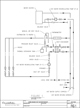
Figure 1.
Hot water recirculation for high-rise buildings has been problematic since high-rise construction began, and it has become more complicated as buildings get taller. The basic systems referred to in the codes, text books and standards work well for shorter buildings but do not address the special requirements of very tall buildings with multiple pressure zones. The hot water return pumps required to overcome the high pressures in these systems bring with them noise and vibration that, if not dealt with properly, will result in complaints from the building’s inhabitants.
As each zone of the building is brought back to the water heater, they arrive at different pressures, and if this difference is too great, one or more zones may refuse to circulate. The pressure-blending valves required to manage these pressure variations require thoughtful and delicate adjustments. This is often beyond the performance capabilities of the installing contractor and must be done by a specialized balancing contractor. Additional problems arise if, after balancing, the operator changes the set point of the pressure-reducing stations or the pressure booster output.
In the past, some engineers have used a water heater in each zone with its own circulating system. This type of decentralized system has fallen from favor due to the space requirements for the equipment, flues, etc., required to support them. They did, however, provide an answer to the difficulties of multi-zoned recirculation systems by neatly sidestepping altogether the issues of combining competing pressures.
In this article, I will describe a system that does the same neat sidestep, as it draws on the methods of reheat that our friends across the aisle in the HVAC department use all the time. But first I must explain how I came about this system.
Whenever a rep wants to show me something, I always make time for him as he may have the device I need that afternoon.
This is what happened when Mark Kaulas of Bornquist, Inc., our Chicago-area Bell & Gossett rep, called a year or so ago. Kaulas and I had been trying for some time, without success, to find a way to simplify high-rise hot water circulation and reheat using small electric water heaters. We found no workable solution as the energy required was too great.
[Author’s Note: Let me note my special thanks to Mark for his help in preparing this article. He is a competent, practical and thorough engineer and a good friend.]
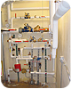
A PRV & Zone Heater Installation. In this
larger system, the heat exchanger is in the middle near the bottom.
Simple And New
Kaulas related the experience of Dave and Jim Attard of California Hydronics Corp. Back in 2004, they were also trying to simplify multi-zone hot water return systems, and they came up with the idea of using the circulated high-pressure hot water supply as the heat source to re-heat the secondary zone through a brazed plate heat exchanger. They ran it by some of the engineers that were working with the design and build contractors, and everyone thought it was a great idea. Consequently, they first tried it out on a high-rise in San Francisco (where it worked great). Since then other ITT representatives have introduced this design in Seattle; Charlotte, NC; Atlanta; and the rest of California.The idea, which is working without complaint in several buildings, was to use a small pump and a brazed plate heat exchanger in each zone to circulate and reheat the hot water locally rather than trying to pump each zone back to the central water heater (seeFigure 1). In this new system, a small pump (P-1) on the low-pressure side of the pressure reducing station circulates water through the risers and heat exchanger, then back to the distribution piping.
The pump must be capable of moving enough water to offset the heat loss through either the insulated piping in the supply and return or the minimum set point that can be achieved by the calibrated balancing valves, whichever is greater. The sizing of the brazed plate heat exchanger must provide enough heat exchange surface to reheat the hot water to within a few degrees of the hot water entering the zone. I am sure the reps will be more than happy to assist in the sizing and selection of the equipment.
The heat exchanger approach temperature should be about two to three degrees Fahrenheit. The other side of the heat exchanger takes its heat supply from the hot water express riser through a calibrated balance valve. Flow in the express riser is driven by a pump (P-2) located near the water heater. This pump must be capable of moving enough water to satisfy both the heat loss for all the hot water supply piping and the heat demand of the heat exchangers against the friction loss of the piping and pressure drop of the brazed plate heat exchanger for each zone in the building.
There are other items in Figure 1 that, although not strictly required for the operation of the reheat system, are strongly recommended for ease of set up, safety and commissioning. A pressure relief valve should be placed in the piping on the low-pressure side of the heat exchanger. If a pinhole leak develops in the heat exchanger, it would allow high-pressure hot water to bypass the pressure-reducing station and overpressurize the hot water zone.
A manual air vent should be arranged at the highest point in the piping after the heat exchanger. This allows for a straightforward easy method of getting the air out of the system during start up, balancing, commissioning and operation. Thermometers should be placed on the inlet and outlet of both the high pressure and low pressure sides of the heat exchanger. These are needed in order to make sure that the required heat transfer is taking place.
Each pump requires a check valve on its discharge, otherwise the water will not know which direction to go upon leaving the pump. Direction arrows on the outside of the piping indicate where water leaks out of the pipe. So check the arrow and make sure water gets back into the pipe. In my experience, once the water gets out, it just lays on the floor. Any pump anywhere in a water distribution system looks naked without pressure gages, so these should be installed on the inlet and outlets of the recirculation pumps. I also call for the installation of an expansion tank because it is easier to put it in than to argue with the plumbing inspector. However, I will readily admit that it is not necessary.
Other considerations for this type of installation are typically the same as any other mechanical equipment, including space requirements for servicing or replacement of parts; a secure location protected from unauthorized tampering; a floor drain with a trap primer; and lighting.
Putting the System Into Service
Now we are ready to turn the whole thing on, get it adjusted and put it into service. These steps are intended to be followed in the order given:1. Verify that the pumps are energized and rotate in the correct direction. (Most pumps will be fractional horsepower but follow this step just in case they aren’t.)
2. Verify that the pressure-reducing station is operational and adjusted properly.
3. Using the manual air vents, remove all entrapped air from both the system side and local side of the heat exchangers.
4. Start the main water heater and bring it to its designed operating temperature.
5. Verify that all calibrated balancing valves are fully open.
6. Start pump P-2 (located at the water heater) and run the pump against a closed discharge valve. Record the pressure and amperage draw at this no-flow point. Open the discharge shut-off valve and adjust the calibrated balance valve to the designed flow rate. Record the valve setting, pressure drop, operating pressure and amperage draw at this duty point. This information should be used to verify that the pump installed is the correct pump. If it isn’t, change out the pump before proceeding.
7. Adjust the calibrated balancing valve (on the system side of the zone closest to the water heater) to its designed flow rate. Record this set point and pressure drop. Continue adjusting the system-side balance valves in order as you move further from the water heater. As these balance valves are adjusted, the flow rate at pump P-2 should be rechecked and adjusted if necessary.
8. Start the P-1 pump on the local zone side of the heat exchanger. Record the operating data as we did for pump P-2 in item 6 above.
9. Starting at the riser closest to the P-1 pump at the heat exchanger, set the balance valve to its designed flow rate. Record the set point and pressure drop. Continue adjusting the balance valves as you move further away from the heat transfer equipment. Record the set points as they are established. Recheck flow rate of the pump P-1 as you proceed and readjust if it becomes necessary.
10. Now the system is up and operating as can be verified by reference to the thermometers on the inlet and outlet of both sides of the heat exchanger. These initial readings should be recorded.
11. Prepare a system balance report that contains all of the data recorded as the system was placed in service. This will be helpful to the building operating personnel.
For larger systems with many risers and zones it is sometimes necessary to set the initial flow of the balancing valves at the pumps 10% greater than the calculated design as the zones or risers are brought on line. This overage goes away without needing to readjust.
It is often desirable to occupy the lower zones of a high-rise building while the upper zones are still under construction. To do this, simply readjust the system-side balance valves as each new zone is put into service.