This is an updated version of the "College of Product Knowledge" product training course introduced by PME's sister publication, Supply House Times, in 1979. This excerpt takes an in-depth look at roof and floor drains and grease interceptors.
Though the singular term "drain" can be applied to a number of product components in the plumbing industry, the plural term "drains" means something more specific (at the distribution level, this is often referred to as a "line of drains.") This latter sense refers to the devices designed to collect water from floors, roofs, parking lots, etc., and transmit it to a connecting drainage system. The heart of most manufacturers' drain lines (and the lion's share of the volume) involves the roof and floor types (although the typical line consists of more than these). Because of the wide variety of installation requirements, there are literally dozens of specific drain designs available today. We don't have space here to hit them all, but we'll do our best to boil all this down to the basic facts for you.
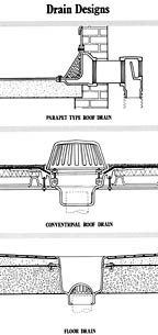
Roof Drains
The purpose of a roof drainage system is to receive rainwater and convey it to the street, sewer facilities or other means available for its disposal. Several factors must be considered in the proper specifying of such a drainage system. One has to do with the purpose of the roof--whether it is designed to rapidly dispose of rainwater, or to serve as a storm water retention area, discharging flow at a slowly controlled rate. Other considerations that affect drain design selection include the intended use of the roof and the pitch. As examples, some roofs are used for cooling purposes, where a predetermined level of water is maintained, or a constant sprinkler effect is used during hot periods of the year. Other roofs are used as promenades and terraces, or in some cases, for parking. One of the most important factors to consider in drain specification, however, is the "maximum rainfall per hour" rate in the region of the country involved. Such data is available for all parts of the U.S., and is extremely important in designing roof drainage systems capable of handling the maximum in downpours without excessive and economically wasteful capacity.Though there are numerous specific designs, the standard roof drain includes five basic components:
- 1) Body: A heavy-duty sump construction, necking down to join to the connecting drainage pipe (called the leader).
2) Dome: A metal or plastic dome-shaped grate that prevents debris from washing into the drain.
3) Deck Clamp: A ring that mounts from the underside of the roof, connected to the top flange of the drain body by means of perimeter bolts. The compression clamp action provided by the tightening of the nuts gives a secure mounting of the drain to the roof, preventing any movement and sealing against any seepage around the installation.
4) Drain Receiver: This recessed metal flange supports the drain body, distributing that load (and that of the connecting piping) over a broader area than would be the case with the body flange alone. It also compensates for irregular or off-center drain openings in the roof.
5) Extension: For installations in which insulation is applied to the deck, extension components of various heights are available that raise the position of the dome. Another design approach to this same function involves the use of a threaded collar that can be adjusted to whatever height is required.
In addition to these more common roof drain designs, there are other variations that involve flat grates for promenade areas and "parapet" types to convey water through short walls above roof level.
Floor Drains
As the name indicates, this type of drain is designed to remove wastewater from floor areas and discharge it into the connecting waste and sewer system. Actually, there are a few more functions involved, accounting for the number of specification factors that must be considered. In addition to receiving and transferring liquid wastes, the floor drain must strain out larger sized solids, often support pedestrian and/or vehicle traffic, and provide the appropriate appearance for the installation (in terms of material and design). The selection of floor drains for small factories where floors are not subject to heavy or specialized traffic is relatively simple. There are, however, a variety of buildings with specialized drainage needs, requiring special designs. An example would be a hospital, where floors must be kept scrupulously clean. Here, the drains must be provided with attractive metal tops and finished to blend into the overall architectural design--yet be sufficiently strong to support the weight of carts and other equipment that might be rolled over them. For added sanitation, drain interiors with acid resisting enamel finishes are often specified.Factory installations involving traffic from heavy vehicles require drain designs with special load bearing capability. Adequate drainage volume capacity is especially important for shower and toilet rooms, as well as areas subject to emergency sprinkler discharge, such as boiler rooms, shop and yard areas. In parking garages, car repair shops and service stations, where oil debris can cause potential fire hazards, special drains must be provided that separate the volatile liquids and keep them from entering the connecting sewer. There are many more specialized installation requirements, but this overview gives you the basic idea that there is no such thing as an "all-purpose standard floor drain."
In terms of construction, a typical floor drain design consists of a body with a sump area that necks down to connect to the drainage line. A ring-like flashing clamp traps a waterproof membrane in the floor to prevent seepage around the installation. This is usually clamped into place by bolts. On some models, an adjustable collar mates with the clamping flange to provide height adjustment in relation to the finished level of the floor. Common strainer tops include the flat grate type, designed with a flat grate and strainer bucket below (for handling wastewater with a high percentage of debris), and a heavy-duty "tractor" grate that includes a supporting skirt around the perimeter.
Typical specification considerations for floor drains include the size of the top and outlet, the construction of the floor involved, the weight of traffic to be encountered, the material makeup of the drain, possible sediment-trapping requirement, the type of connection to the drain system, the appearance, and compliance with local code requirements. Specialized trap designs include types that incorporate built-in traps, and those with devices to prevent backflow (essentially large check valves to keep drain water from backing up due to a reversal in the system).
Interceptors
Our last category of products in this section concerns devices designed to intercept grease, oils and solids from water before they enter and possibly clog the drainage system. (Separate product designs are made to handle each of these substances.) Probably the most common of these interceptors is the grease type, because of countless restaurant and other commercial kitchen applications. Most product designs in this category work something like this: Wastewater draining into the interceptor passes through a flow control fitting that regulates the velocity, permitting non-turbulent entry into the interceptor tank. As the water enters at this controlled rate of flow, it passes over a series of separator baffles and cascades designed to cause greases, fats and oils to become separated and released from the wastewater. Once released, these contaminants rise to the top of the chamber by natural flotation (they're lighter than water), where they accumulate until removed.Removal of the grease (referred to as "drawing off") is accomplished by first running hot water through the drain to liquefy it. Then a shutoff valve downstream from the tank is closed, forcing the flow to pass through the top of a draw-off pipe or hose (hot water is running down the drain all this time, creating the flow). Since the grease has collected at the top of the tank, it flows out of the draw-off line first. The discharge eventually becomes clear in color, indicating that most of the grease has been removed; the shutoff valve is then reopened and the hot water turned off. Such a procedure is performed on a regular basis. (For more information on grease interceptors, see the Equipment Overview on page 50 of the November 2002 issue.)