Despite the popularity of this system in Europe and its increased application around the world, siphonic drainage is virtually unknown in the United States. Roof drainage is probably one of the most crucial of the fundamental building mechanical systems. For the most part, roofs in the United States have been drained of rainwater the same way as they have been for centuries. Building and plumbing codes clearly outline the minimum requirements for rainwater pipe systems drawing off of tried and true techniques.
Traditional Methods of Roof Drainage
Traditional rainwater drainage piping is designed to operate partially full under atmospheric pressure, although it may be surcharged under extreme conditions. To induce water flow, horizontal piping must be pitched. The greater the pitch, the faster water will travel along the pipe in accordance with the Manning Formula well known to plumbing and civil engineers (Equation 1). The main premise of the Manning Formula is open channel flow with no head pressure driving this flow.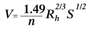
Equation 1 Manning Formula
In the Equation 1, V is the fluid velocity in feet per second, n is the dimensionless roughness factor that is a property of the channel surface, Rh is the hydraulic radius in feet and S is the channel slope. The water velocity in a 4-in. cast iron (n = 0.012) gravity drainage pipe pitched at a 1% slope is 2.34 feet per second when running half full. It can flow 44.5 gallons per minute. This formula is the basis for the calculated tables included in model codes.
Plumbing engineers who design rainwater pipe systems are constrained by state or local plumbing codes that prescribe minimum requirements. These codes specify the minimum required pitch of piping and the maximum roof area that can be collected by horizontal and vertical pipes. The purpose of these codes is to enforce uniform application of fundamental principles of open channel flow in piping and ensure the safety of roof structures. The existence of these codes, however, does not preclude alternative designs if properly engineered. With the involvement and understanding of local enforcement authorities, it can be possible to use siphonic systems.
Does Roof Drainage Need to Be Atmospheric?
Obviously, proper drainage of waste from plumbing fixtures in a building is achieved only if atmospheric pressures are maintained within the piping system. Venting and pipe sizing requirements in plumbing codes ensure this condition is maintained so fixture traps do not get siphoned off under negative pressures. These installation requirements also ensure sewer gas does not get blown through fixture trap seals under positive pressures.
With roof drainage, however, the pipe interior pressures can be positive or negative since trap seals are not installed in storm water systems (apart from old systems tied to a combined sewer). Pipe systems may also run completely surcharged during extreme rainfall conditions, something not desirable in a sanitary waste system. It is therefore possible to increase the efficiency of roof drainage by designing the piping to operate completely charged with water. In this condition, however, different assumptions about the hydraulics must be made to predict system pressures and flows.
The Principles of Siphonic Systems
The Manning Formula, shown as Equation 1, is a derivative of the more general friction loss theory of Darcy-Weisbach and from BernoulliOs Principle. Manning makes the assumption of open channel steady flow where the free surface of the water (i.e. the hydraulic grade line) is parallel with the slope of the channel and at atmospheric pressure. Water in pipes running full, however, may not meet these conditions.
BernoulliOs Equation is an energy balance relationship that basically states that a fluid in either rest or in motion possesses three fundamental forms of energy. A fluid has a static pressure energy that represents the work energy expended in compressing the fluid. It also has a kinetic energy as a result of motion. Finally, it also possesses potential energy as a result of its elevation in a gravity field. The total of all of these energy forms, according to Bernoulli, is balanced even though the individual pressure, velocity or potential energy conditions may change. In mathematical form, BernoulliOs theory is expressed as Equation 2 here.
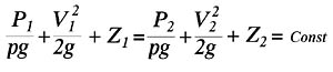
Equation 2 Bernoulli's Principle
This equation assumes that the fluid is both incompressible (e.g. has constant density) and frictionless. Basically, any two points within a fluid possess a constant energy.
Obviously, the frictionless assumption of Bernoulli is made to demonstrate a basic principle of energy conservation. However, real fluid flow in a pipe experiences energy loss due to viscous effects, according to the Darcy-Weisbach Equation shown in Equation 3.
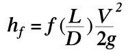
Equation 3 Darcy-Weisbach Equation
In Equation 3, hf is the friction head loss in ft-pounds per pound of fluid, L is the pipe length in feet, D is the pipe inner diameter in feet, V is the fluid velocity in feet per second and g is the gravitational constant. The f term is a dimensionless friction factor found from the Colebrook Equation or the Moody Diagram, and is a function of the fluid Reynolds Number and pipe surface roughness. When friction loss is taken into account, Equation 2 becomes Equation 3 here.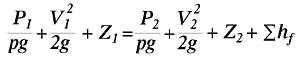
Equation 4 Bernoulli with Energy Loss
Consider a simple roof drainage system consisting of a single drain on a roof at height Z1 connected to a pipe that runs horizontally and then drops to grade level at height Z2 and discharges to an atmospherically vented manhole. The fluid pressure at both the drain entrance (P1) and the point of discharge (P2) are at atmospheric and therefore cancel out of Equation 4. The velocity (V1) near the drain inlet and in the manhole chamber (V2) are essentially zero and also fall out of Equation 4. The remaining terms, rearranged, are as follows in Equation 5.
Equation 5
Equation 5 is the basic governing equation of a siphonic roof drainage system. In short, the total energy available to a siphonic system is equal to the potential energy from the elevation difference between the roof outlet and the point of discharge. The flow (i.e. kinetic energy) induced in the system by the conversion of this potential energy results in an energy loss from friction equal to the available potential energy. The height difference in Equation 5 is referred to as the Disposable Head.
People often make the incorrect statement that a siphonic system is not a gravity system. Traditional gravity drainage operates at atmospheric pressure throughout the pipe system and relies on the physical gradient of horizontal piping to induce flow. While a siphonic system operates under different physical conditions, it still works under the influence of gravity, as the Disposable Head term on the left side of Equation 5 shows. Without gravity, a siphonic system does not work.
Siphonic Operation
The total friction loss is the sum of the losses throughout all system components, including pipe, fittings and the outlets. By manipulating pipe diameters, lengths and fittings, the engineer can control the rate at which water drains off of the roof. This flow rate, divided by the overall roof area being drained, is referred to as the Dimensional Rainfall Intensity (DRI). Once installed, the pipe system and the Disposable Head are fixed, and therefore, the flow rate is fixed. No matter how hard it rains in excess of the design DRI, the system discharges at a rate equal to the DRI. The excess will build up on the roof unless relieved through overflow drains or weirs. It is essential that a siphonic system (which may consist of a primary and secondary overflow system) has a total design capacity in excess of the highest anticipated rainfall rate within the lifetime of the building.The key to a siphonic system, apart from the siphonic drain, is the downpipe. Once the piping is filled with water, the column of water in the downpipe wants to fall. The water in the horizontal collector pipe is pulled to the downpipe to replace this water. As a result, the water pressure in the horizontal collector falls below atmospheric. Water on the roof is literally sucked or siphoned into the connected drains.
If it happens to rain at a rate well below the design DRI, the system simply acts like a traditional gravity system with an air-water mixture at atmospheric pressure. The drainage rate in the collector pipe, even when partially full and with no pitch, is surprisingly good. Once the system is fully primed, there is an abrupt increase in system velocities that serve to clean the system of any debris that may have been ingested.
Siphonic drainage flow patterns are a subject of much intensive research. This author had the opportunity to observe the largest test rig in the world at the University of Sheffield in the United Kingdom. Clear sections of piping in the system allow visual observation of the flow patterns.
The Benefits
Siphonic systems are ideal for low-rise buildings with a vast footprint. Such buildings include airport terminals, covered malls, office complexes, warehouses, aircraft hangers, train stations, convention centers and factories. In these buildings, several roof drains can be connected to a horizontal collector that can be routed without pitch to the perimeter of the building.Since sub-atmospheric pressures generated at the top of the downpipe induce water flow, there is no need to pitch horizontal collector piping. In fact, this pipe can be installed perfectly flat. The flows induced by water falling down the downpipe allow the system to operate at flow velocities higher than can be achieved in atmospheric gravity systems. This "full-bore" high velocity flow allows the engineer to specify smaller pipe diameters than would have been prescribed by plumbing codes for traditional gravity systems.
Because siphonic piping does not have to be pitched like traditional open channel drainage, the piping system requires no more space than other pressurized mechanical piping systems. This makes it easier to provide adequate drainage in buildings with challenging architectural limitations with respect to space. Fewer downpipes means fewer chances of interfering with architecture. Because locating downpipes in a siphonic system is more flexible, the design can accommodate not only architectural demands, but also site drainage limitations.
Application in America
Siphonic systems have been installed all throughout Europe and have made their way to Australia, New Zealand, Singapore, Korea, Canada, Mexico, Russia and the Middle East, just to name a few. One siphonic system is currently under design, with authority approval, for a major project in the United States. However, the general acceptance of this system in America has been very slow. As it is now, any siphonic system planned for a project in the United States will require a special variance by the local or state plumbing board of inspectors.A siphonic roof drain system is truly an "engineered system." To design a traditional roof drain system by code, plumbing engineers simply follow prescriptive instructions in the code and read off of pre-calculated, standardized charts. Siphonic systems must be designed with careful and expert analysis otherwise unfamiliar to a majority of plumbing engineers and designers. It also requires the knowledge and understanding of rainfall patterns in the project location.
Coordination between the siphonic system engineer, structural engineer and architect is essential to ensure both the roof strength and waterproofing can tolerate an amount of ponding on the roof. This amount of ponding, however, rarely has to exceed prescribed snow load common in northern states. Siphonic systems, by the nature of their operation, also require secondary overflow systems. However, such systems are currently required by most codes anyway.
The level of technical expertise required from both plumbing engineers, plumbing contractors and local inspectors may have been a disincentive in the use of siphonic systems in the past. All engineers, however, should keep abreast of the latest technologies on the market to better service their clients.