
A 3/4" copper tube is one of the smallest rigid pipes found in most North American hydronic heating systems. It is often used for series circuits of fin-tube baseboard or to supply wall convectors. After touring some “classic” North American installations, a newcomer might conclude there’s little use for tubing smaller than 3/4" with the possible exception of radiant panel circuits.
So how much heat can a 3/4" copper tube deliver? The answer depends on assumptions made for maximum flow rate and circuit temperature drop.
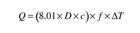
Where:
Q = rate of heat transport (Btu/hr)
D = fluid density at average circuit temperature (lb/ft3)
c = specific heat of fluid (Btu/lb/°F)
f = flow rate (gpm)
∆T = temperature drop of circuit (°F)
8.01 = units factor
For water at an average temperature of 140°F, the product (8.01 x D x c) equals 490. For 30% glycol, it’s 479, and for 50% glycol, it’s 450.

bviously, the assumed maximum flow rate greatly affects the maximum heat transport rate.
So does the circuit temperature drop? The assumption that a hydronic circuit always “wants to” or should operate with a 20°F temperature drop has beset the hydronics industry for decades. There is nothing necessarily correct about a circuit operating with a 20°F temperature drop.
Many hydronic systems provide proper heat delivery when operating at far lower as well as far higher temperature drops. For example: I’ve personally observed radiant floor circuits maintaining excellent comfort while operating with temperature drops of only 2-5°F. Why does this happen? Because flow through the circuit is much higher than the designer anticipated. Why does this happen? Because the circulator is probably well oversized for the required flow and head loss. So what’s the problem? Wasted electrical energy.
Overpumping is currently a serious problem within the North American hydronics industry. It exists in “rule-of-thumb” systems that follow existing traditions as well as “fully engineered” systems in larger buildings.
Correcting this situation represents a great opportunity to demonstrate the “greenness” of hydronic heating at a time when many North Americans seem willing to listen to the advantages of green building technology.
A Synergistic Approach
Imagine a new 2,500-sq.-ft. North American house with a design heat load of 25 Btu/hr/square foot (total heating load of 62,500 Btu/hr). This is not an exceptionally low energy use house, but instead typical of a “spec house” in a new suburban development. It’s representative of tens of thousands of new homes built in North America each year as well as hundreds of thousands of existing structures.The house has eight rooms, and the owners want it equipped for room-by-room temperature control. For simplicity we’ll assume all the rooms have the same design heating load of approximately 8,000 Btu/hr each.
The hydronic system selected for this home is shown in Figure 1.
The system’s heat source is a modulating/condensing (mod/con) boiler that supplies both space heating and domestic water heating.
In the space heating mode, the boiler fires as necessary to maintain the water temperature within a small well-insulated buffer tank that also serves as a mounting stand for the boiler and support structure for the near-boiler piping components. The boiler’s outdoor reset controller calculates the target water temperature in the tank. At design load the water is maintained at 160°F. As outdoor temperature increases, the target tank temperature decreases. When the outside temperature climbs to 65°F, the tank is maintained at only 80°F. Above 65°F outdoor temperature, the space heating mode of the system is disabled.
The thermal mass provided by the 20-30 gallons of water in the buffer tank allows the rate of heat generation to be different from the rate of heat released by the heat emitters. This minimizes the potential for boiler short cycling, when only one or two heat emitters are active. Short cycling, if allowed, shortens the life of ignition and combustion components. It also lowers combustion efficiency and increases emissions. Although boiler modulation certainly helps in reducing short cycling, the lowest stable operating rate of present generation mod/con boilers is about 20% of their full-rated output. When a “microload” as small as perhaps 1,000 Btu/hr is present, only thermal mass can produce reasonably long firing cycles.
Low-flow velocities within the tank prevent interference between the boiler circulator and distribution circulator (e.g., provide hydraulic separation). These low-flow velocities let air bubbles rise to the top of the tank where they can be vented, and allow any sediment entering the tank to settle to the tank bottom where it can be periodically flushed out. Thus, the tank provides five complementary functions within this system.
During a call for domestic water heating, the small circulator (P2) connecting the boiler to the buffer tank is temporarily turned off while circulator (P1) operates. The boiler operates at an elevated temperature of 160°F -180°F to provide rapid heat transfer through the DHW tank’s internal heat exchanger. As soon as the DHW cycle is completed, the boiler returns to space heating mode.
The system uses steel panel radiators for space heating. Such panels are very adoptable to different interiors. They come in a variety of heights, widths and depths that allow them to fit into a wide variety of situations. Being relatively light, they can be supported by almost any wall. Their low thermal mass allows them to respond quickly to changes in heat load or internal heat gain. Panel radiators also lend themselves to room by room zoning using non-electric thermostatic radiator valves: Fully modulating room-by-room comfort control without any thermostat wires.
Another benefit of panel radiators is their ability to operate at a relatively high ∆T and correspondingly low-flow rate. In Europe, panel radiators are commonly operated at a 20°C (36°F) temperature drop under design load conditions. These high ∆Ts are possible because panel radiators don’t need to provide the “barefoot friendly” feeling expected from residential radiant floors. Such high temperature drops allow for significant reductions in flow, which in turn reduces pipe size and circulator power without compromising comfort.

Running the Numbers
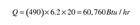
For the system being discussed, let’s assume each panel radiator delivers 8,000 Btu/hr at design load and that the water temperature supplied to the panels at design load is 160°F with a temperature drop of 40°F. This makes the average water temperature in the panels 140°F at design load. The relatively low 120°F return water temperature also allows the mod/con boiler to operate in a partial condensing mode for higher efficiency.The “double water plate” panel radiators selected for the system measure 24 inches high by 72 inches long by 4 inches deep (see Figure 2). Such panels are rated to release 8,400 Btu/hr when operating at an average water temperature of 140°F in a room with 68°F air temperature. They come equipped with integral balancing valves, and can be configured with dual isolating valves at the supply/return connections.

This piping configuration is called a homerun distribution system. It provides several advantages. For starters, the small flexible tubing can be routed through the framing cavities of the building much like electrical cable. The ability to “fish” tubing through closed framing cavities is a tremendous advantage over rigid tubing, especially in retrofit situations.
Homerun systems also deliver equal water temperature to each heat emitter. This simplifies sizing since the temperature drop associated with series-type circuits is not present.
In combination with thermostatic valves at each radiator, homerun systems allow room-by-room temperature control. The master bedroom can be kept cool for sleeping while the master bathroom remains toasty warm for the morning shower. Unoccupied rooms can be set at lower temperatures to conserve fuel. Internal heat gains from sunlight, equipment or people are compensated for without adversely affecting comfort in other rooms.
The classic choice for producing flow in such a system is a fixed-speed, wet-rotor circulator. Current practice also calls for a differential pressure bypass valve to prevent excessively high differential pressure across the manifold station when only one or two zone circuits are active.
Although this approach works, and has been used in thousands of systems, a far better solution is now making its first appearance in North America. That solution is a differential pressure regulated circulator with an electronically commutated motor (ECM). An example of such a circulator is shown in Figure 3.
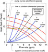
ECM-based circulators use a microprocessor and “memory mapped” electrical operating characteristic to continually determine the differential pressure at which they operate. No external pressure sensors or transducers are required. Such circulators can be set to maintain a fixed differential pressure regardless of how many zone circuits happen to be open. They do so by varying motor speed so that the intersection of the pump curve and current system head loss curve remain at the set differential pressure as shown in Figure 4.
As a thermostatic radiator valve changes flow, the circulator senses an “attempted” change in differential pressure and increases or decreases motor speed to compensate for it. This eliminates the need for a differential pressure bypass valve and significantly reduces electrical consumption during part-load conditions.
When the system reaches design load conditions (e.g., all zone circuits fully open) the ECM-based circulator operates at approximately twice the wire-to-water efficiency of a typical PSC (permanent split capacitor) wet-rotor circulator. Stated another way, the same flow is achieved using half the electrical wattage.
If all zone circuits are closed, the circulator automatically drops to a very low wattage standby mode and awaits a drop in differential pressure, indicating one or more of the thermostatic valves have begun to open. At that point it resumes normal constant differential pressure regulation. If outdoor air temperature rises above 65°F power to the circulator as well as the boiler is turned off.
Simulated Reality
The hydraulic performance of the example system was modeled using the Hydronics Design Studio software. Doing so requires specified lengths of tubing as well as head loss information for the panel radiator.Based on manufacturers’ data, the head loss of the panel radiator is mostly that of the integral valve body. The multiple parallel risers in the two wetted plates of the panel reduce head loss of the panel body to almost zero.
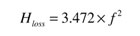
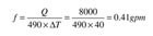
Where:
Hloss = head loss of panel (feet of head)
f = flow rate (gpm)
It’s also possible to express the head loss of the panel as an equivalent length of tubing (e.g., the length of a specified tube type/size that has the same head loss as the radiator). The selected panel radiators have the following equivalent lengths:
The first system simulation was based on the use of 3/8” PEX tubing for all homerun circuits, which were assumed to be 75 feet of supply plus 75 feet of return tubing. The copper manifolds were assumed to be 1" copper.
Using a Grundfos UPS15-58 on low speed (60 watts rated power consumption), each panel would receive a flow of 0.52 gallons per minute, which is more than sufficient for the required performance. Temperature drop across the panel radiators at this condition would be 31.4°F.
Imagine, 60 watts of circulator input power supplying over 64,000 Btu/hr to this house under design load conditions. This is a fraction of the circulator wattage used in many current residential systems of similar capacity.
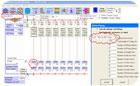
Another simulation was run assuming 1/2” PEX-AL-PEX tubing for all homerun circuits. The circulator was changed to a Taco 003 (nominal 40-watt electrical input). Flow through each panel changed very little (0.51 gpm per panel). The slightly larger tubing allowed a nominal 20-watt decrease in circulator input with virtually the same flow and same thermal performance. A screen shot of the simulation is shown in Figure 5.
Keep in mind that both simulations were for design load conditions and for circulators using traditional PSC motors. An ECM-based circulator would further reduce input wattage. Under partial load there may even be times when the required circulator input wattage would be less than 10 watts. To put this in perspective, a typical plug-in “black box” DC power adapter for a cable modem draws about 21 watts.
Now Is The Time
The North American hydronics industry has a tremendous opportunity at hand in the form of homerun distribution systems combined with ECM-based pressure-regulated circulators. The parallel topology of homerun systems allows for major reduction in circulator power while also providing room-by-room comfort control and simple/fast installation. Homerun distribution systems are ideally suited for an ECM-based variable speed circulator. European studies have shown electrical energy savings of 60+% in comparison to PSC-type circulators of equivalent peak performance. These studies have also shown paybacks on the incrementally higher installation cost of ECM-based circulators of less than 3 years.¹As America continues to embrace “green” technology, it’s time for our industry to demonstrate its ability to deliver unsurpassed comfort using a fraction of the distribution energy required by forced air systems. Although homerun distribution systems and ECM-based circulators are far less visible to the public than are solar collectors and wind turbines, they offer far superior returns on investment. It’s time to tell our side of the green story!
1 Energy + Pumps Project: http://www.energy pluspumps.eu/en/cesky/Aboutproject/what_is.html.

